


Manual
2100-468E
Page
15 of 27
THERMOSTAT INDICATOR LAMPS
The red lamp marked “EM. HT.” comes on and stays on
whenever the system switch is placed in Em. Ht. position.
The green lamp marked “Check” will come on if there is
any problem that prevents the compressor from running
when it is supposed to be.
EMERGENCY HEAT POSITION
The operator of the equipment must manually place the
system switch in this position. This is done when there is a
known problem with the outdoor section, or when the green
“Check” lamp comes on indicating a problem.
TRANSFORMER TAPS
230/208V, 1 phase and 3 phase equipment employ dual
primary voltage transformers. All equipment leaves the
factory wired on 240V tap. For 208V operation, reconnect
from 240V to 208V tap. The acceptable operating voltage
range for the 240 and 208V taps are:
TAP
RANGE
240
253 – 216
208
220 – 187
NOTE: The voltage should be measured at the field
power connection point in the unit and while the
unit is operating at full load (maximum amperage
operating condition).
COMPRESSOR CUTOFF THERMOSTAT
and OUTDOOR THERMOSTAT WIRING
Heat pump compressor operation at outdoor temperatures
below 0°F are neither desirable not advantageous in terms
of efficiency. Since most equipment at time of manufacture
is not designated for any specific destination of the country
and most of the equipment is installed in areas not
approaching the lower outdoor temperature range, the
compressor cutoffs are not factory installed.
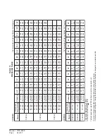
Outdoor thermostats are available to hold off various banks
of electric heat until needed as determined by outdoor
temperature. The set point of either type of thermostat is
variable with geographic region and sizing of the heating
equipment to the structure. Utilization of the Heating
Application Data and the heat loss calculation of the
building are useful in determining the correct set points.
Refer to Installation Instructions of CMH-14 Outdoor
Thermostat Kit for more information.
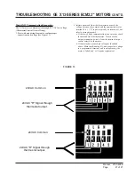
FIGURE 7
UNIT 24V TERMINAL BOARD ( 5 — 10 KW)
MIS-2151
D1
Outdoor Fan Motor
Control
Yellow
Yel/Brn
Terminal
Outdoor
Block
Y
C
G
R
Y1
B
DH
Black
Safety
W1
Compressor
Factory Jumper
W2
Yellow
E
W3
Unit Control Panel
Unit 24V
Heat
Brown
Remove
Relay
used as
"Y to Y1"
Yel/Brn
Cutoff
L
Blue
Thermostat
Heat Pump
Control
(Partially Shown)
Low Ambient
Optional Field Wiring
2
1
3
5
1
3
2
4
6
L
Note: Factory set on 60 min.
cycle. Reconnect on 30 min.
for 30 min. cycle or 90 min.
for 90 min. cycle.
SPEEDUP
JMP
SEN
30
60
90
NC
NO
COM
R
W2
R
Y
CC
L1
C
C
LO
B
RV
SENSOR
OFM


