


Manual 2100-671
Page
19 of 44
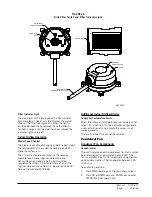
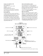
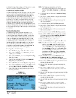
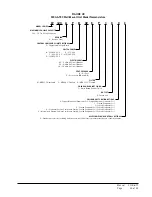
FIGURE 25
Dirty Filter Switch and Filter Indicator Light
SCREW TO
REMOVE COVER
COVER
TUBE LOCATED IN
AIRSTREAM AFTER FILTER
MIS-3952
INDICATOR ARROW
ADJUSTMENT
ADJUSTMENT
KNOB
FILTER LIGHT
MIS-3952
Filter Indicator Light
The wall-mount unit is equipped with a 24v indicator
light mounted on side of unit that displays the current
status of the filter (see Figure 25). When the light is
on, the filter needs to be replaced. Once the filter(s)
has been changed and the alarm has been cleared, the
indicator light will turn off.
Indoor Airflow Operation
Blower Speed Control
The blower is capable of changing speeds to best match
the requirements of the system depending on which
mode the system is in.
The unit will automatically switch to the required
speed for each mode. High sensible mode and
dehumidification mode are both communicated
separately from the LC. For more information on the
high sensible command from LC, please see LC6000
Service Instructions 2100-669.
Additional Indoor Airflow Alarms
Supply Air Temperature Alarm
When the supply air temperature sensor value is out of
range (-41.0 to 303.0°F), the controller will generate
a sensor failure alarm to indicate the sensor is not
working properly.
This alarm is fixed and cannot be adjusted.
Condenser Fan
Condenser Fan Components
Condenser Fan
The unit is equipped with a condenser fan that is driven
by an electronically commutated motor (ECM). This
fan is controlled by a 0-100% command using modbus
serial communication. The fan operates between 100-
1200 rpm.
To enable fan override:
1. Press MENU key to go to the Main Menu screen.
2. Press UP or DOWN keys and ENTER key to enter
TECHNICIAN password 1313.


