


Manual 2100-671
Page
13 of 44
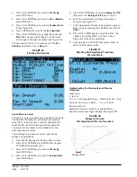
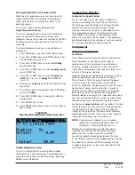
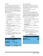
To change or view the unit setpoint:
1. From the Status screen, press UP or DOWN key
until Quick Menu displays Setpoints icon ( ).
Press ENTER key.
2. Press ENTER key to scroll to
Cool
Setpoint
or
Heat
Setpoint
(see Figure 4 on page 8).
3. Press UP or DOWN keys to change the value to
desired heating and/or cooling setpoint.
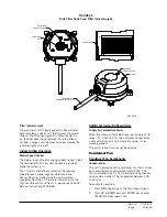
Orphan Mode
MEGA-TEC Series wall-mount units have the capability
to run without the LC6000 controller attached—this
feature is called orphan mode. This keeps the shelter
between 60°F and 77°F (factory default settings) by
the use of the factory-installed return air sensor in
each wall-mount unit. In orphan mode, no auxiliary
temperature measurement devices are required for
operation. The wall-mount unit automatically uses a
continuous blower setting to circulate room air into
the return air inlet and uses the return air temperature
sensor to control room temperature.
If at any time the wall-mount unit(s) loses
communication with the LC6000 controller, the wall-
mount unit(s) will go into orphan mode and operate
using the last communicated setpoints.
To change default setpoints, refer to
Setpoints
on page 8.
During installation, the ability to run in orphan mode
allows deactivation of one of the existing, older wall-
mount units, while keeping the shelter cool with the
other unit still operating. Once the first of the Bard
wall-mount units is installed and powered on, it will
operate in orphan mode—keeping the climate inside
the shelter stable and the installers comfortable while
the remainder of the older equipment is removed and
the remaining Bard wall-mount units and LC6000
controller are installed.
Additionally, should any or all of the MEGA-TEC Series
wall-mount units lose communication with the LC6000
controller (such as during maintenance), they will
continue to serve the shelter’s needs until a repair can
be made.
LC6000 Control
When the unit is connected to a LC6000 supervisory
controller, the cooling and heating stages will be
controlled by the LC6000. For more information on
LC6000 staging, see latest version of LC6000 Service
Instructions 2100-669.
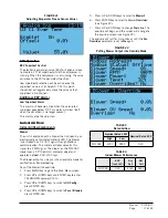
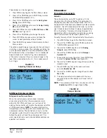
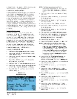
Cooling (with Economizer)
If equipped with an economizer, the unit is equipped
with 1 stage of free cooling and 3 stages of mechanical
cooling for a total of 4 cooling stages (see Figure 13).
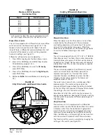
Cooling (without Economizer)
In a situation where the unit is either not equipped
with an economizer or is equipped with an economizer
but the outdoor conditions are not favorable for
economizer operation, the staging will use Stage 1, 2
or 3 differentials (see Figure 14 on page 14).
Heating
The unit can be equipped with 0, 1 or 2 stages of
electric heat (see Figure 15 on page 14).
FIGURE 13
Cooling (with Economizer)
Cooling Deadband
Off
Cooling
75.0°F 75.5°F 76.0°F 76.5°F 77.0°F 77.5°F 78.0°F 78.5°F 79.0°F 79.5°F 80.0°F 80.5°F 81.0°F
Compressor 1 Stage 1
Free Cooling
Compressor 2
Compressor 1 Stage 2


