


Manual 2100-671
Page
26 of 44
Damper Blade
The system utilizes three damper blades to bring
in outdoor air and exhaust space air for economizer
operation. Damper 1 is left intake, damper 2 is exhaust
and damper 3 is right intake. Damper blades are made
of sheet metal and are integrated into the equipment.
To view damper blade position:
1. Press MENU key to go to the Main Menu screen.
2. Press UP or DOWN keys and ENTER key to enter
TECHNICIAN password 1313.
3. Press UP or DOWN keys to scroll to
I/O Config
;
press ENTER key.
4. Press UP or DOWN keys to scroll to
Analog
Outputs
; press ENTER key.
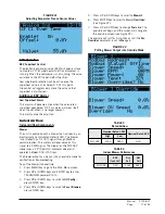
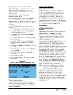
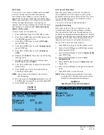
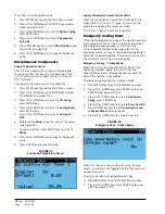
5. Press UP or DOWN keys to scroll to
Damper Intake
Lt 2/5
(see Figure 35),
Damper Intake Rt 3/5
or
Damper Exhaust 1
.
Damper Switch
The economizer utilizes three magnetic switches (one
on each damper blade) to determine if the damper is
operating correctly. This switch will be closed when the
damper is closed and open when the damper is open.
To verify the status of the switch:
1. Press MENU key to go to the Main Menu screen.
2. Press UP or DOWN keys and ENTER key to enter
TECHNICIAN password 1313.
3. Press UP or DOWN keys to scroll to
I/O Config
;
press ENTER key.
4. Press UP or DOWN keys to scroll to
Digital Inputs
;
press ENTER key.
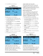
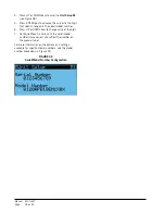
5. Press UP or DOWN keys to scroll to
Digital Ins 2/2
.
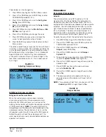
6. Reference the values for
Damper 1
,
Damper 2
,
Damper 3
and
Damper 4
(see Figure 36).
7. The input will display
ON
when the damper is
closed (reflecting closed circuit on damper switch)
and will display
OFF
when the damper is open
(reflecting open circuit on damper switch).
Damper Failed to Open Alarm
When the controller commands the economizer damper
actuator to a position other than 0% and the damper
switch indicates the damper is not open, after a delay
of 20 seconds the controller will generate a damper
failed to open alarm. This alarm is just a notification
and will not disable any features on the controller.
The alarm must be cleared by a user reset.
Damper Failed to Close Alarm
When the controller commands the economizer damper
actuator to the 0% position and the damper switch
indicates the damper is not closed, after a delay of 300
seconds the controller will generate a damper failed to
close alarm. This alarm is just a notification and will
not disable any features on the controller.
The alarm must be cleared by a user reset.
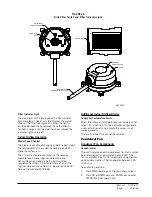
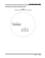
Outdoor Temperature and Humidity Combination Sensor
The unit is equipped with a combination outdoor
temperature and humidity sensor to monitor
outdoor conditions for the economizer operation.
The temperature is measured with a 10k ohm NTC
thermistor. The humidity is measured with a humidity
sensor that outputs a 4-20mA signal to the controller.
The outdoor temperature can be verified by:
1. Press MENU key to go to the Main Menu screen.
2. Press UP or DOWN keys and ENTER key to enter
TECHNICIAN password 1313.
3. Press UP or DOWN keys to scroll to
I/O Config
;
press ENTER key.
4. Press UP or DOWN keys to scroll to
Analog Inputs
;
press ENTER key.
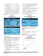
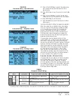
5. Press UP or DOWN keys to scroll to
Analog Ins
4/19
.
6. Reference the
Value
to see the input of the sensor
(see Figure 37).
7. To apply an offset, press ENTER key to scroll to
Offset
.
8. Press UP or DOWN keys to change to the desired
value.
FIGURE 35
Damper Blade Position
FIGURE 36
Damper Switch


