Manual 2100-614K
Page
20 of 61
Email Addresses
– Add up to 10 valid email addresses
that will receive the email notification.
Subject
– Customize the subject line of the email
notification.
Message
– Add a custom message to the notification to
include relevant information regarding the equipment or
building the equipment is installed on.
Send Mail if the Following Alarms Occur
– Select the
alarms that will generate an email notification.
Once all of the information above has been set, be sure
to check that the email notifications are working by
pressing the button “Send test e-mail to first address”.
As the button indicates, this test email will only be sent
to the email address in the first box. When the button
is pressed the message will contain “MC4001 Test
Message!” When the message is generated by an event
it will contain the status of all alarms the controller
offers.
Example:
ALARM : Fire/Smoke
CLEAR : Controller Failure
CLEAR : 2nd Stage Cooling
CLEAR : Low Temperature
CLEAR : High Temperature 1
CLEAR : High Temperature 2
CLEAR : Power Loss System 1
CLEAR : Power Loss System 2
CLEAR : Refrigerant Lockout System 1
CLEAR : Refrigerant Lockout System 2
CLEAR : Generator Active
SNMP
Enable the Traps
Ensure that the check box is checked next to “Enable
SNMP". After enabling SNMP, select which events will
generate traps by checking the box next each item that
should generate a trap.
Network Traffic Limitation
The CB5000 Series has limitations regarding how fast
the controller can be polled for data. It is recommended
that polling be limited to no faster than once per
minute. In addition to this, it is also recommended
that the network administrator for the network in which
the device will be connected is contacted regarding a
network inventory scan. If the network has a scheduled
network scan, the IP address assigned to the controller
should be added to an exclusion list. The network scan,
in addition to the scheduled polling, can cause the
communication board to lock up and require a power
cycle before communication can be re-established.
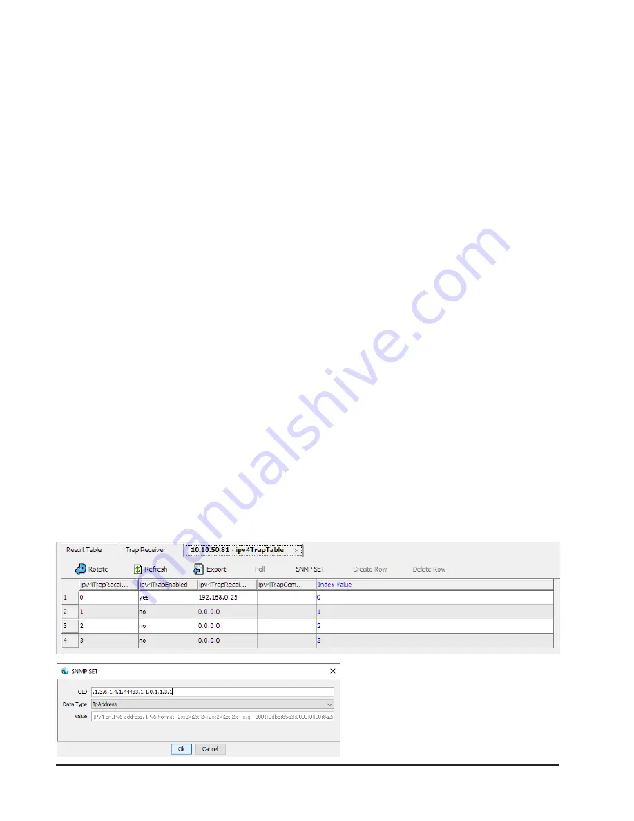
Set the Trap Destination
The configuration of the controller through SNMP will
require the MIB file and an MIB browser to set the trap
destination. The MIB file for the SNMP configuration
on the controller is available at http://bardhvac.com/
software-download. Once the file has been downloaded,
be sure to unzip the file before opening the MIB file in
an MIB browser. Enter the IP address of the controller
into the MIB browser and, with the MIB loaded,
navigate through the MIB tree to Setup>ipv4TrapTable
> ipv4TrapEntry and open the IPv4 in Table View as
shown in
Set Trap Destination
.
NOTE:
ipv6TrapTable is configured to operate with IPv6.
The ipv4TrapEnabled needs to be set to Yes and
ipv4TrapReceiverIPAddress need to be set to the
destination IP address for the traps. This can be
configured for up to four destinations by setting these
two settings for each row within this table (see
ipv4
Trap Table
).
ipv4 Trap Table


