10. Advanced operation
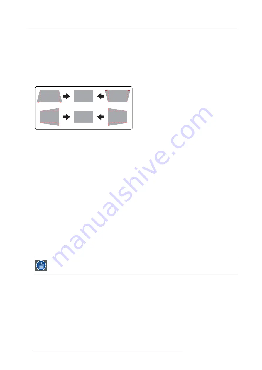
10.1.2 Keystone correction work
fl
ow
Adjusting vertical and horizontal keystone
1. Open the Geometry edit dialog for 2 x 2 mode. See "Selecting the geometry level ", page 70. The default selected anchor point
is the left top corner of the image.
2. If required, select another anchor point of this level (i.e. corner points). See "Selecting an anchor point", page 71.
3. Move the selected anchor point to the desired position. See "Moving an anchor point in small steps", page 72 and "Moving an
anchor point in large steps", page 73.
Note:
Anchor points should only be moved inside the visible image area since moving an anchor point to the outside causes
loss of image content.
Image 10-6
Keystone correction
4. Select each of the other anchor points in this level in turn and move them to the desired position to end up with a perfectly
rectangular image.
10.1.3 General geometry adjustment work
fl
ow
Performing geometry adjustment
1. Open the Geometry edit dialog for 2 x 2 mode. See "Selecting the geometry level ", page 70. The default selected anchor point
is the left top corner of the image.
2. If required, select another anchor point of this level. See "Selecting an anchor point", page 71.
3. Move the selected anchor point to the desired position. See "Moving an anchor point in small steps", page 72 and "Moving an
anchor point in large steps", page 73.
Note:
Anchor points should only be moved inside the visible image area since moving an anchor point to the outside causes
loss of image content.
4. Select each of the other anchor points in this level in turn and move them to the desired position.
5. Then, select each of the anchor points of the next lower level in the selected geometry mode and adjust their position.
6. Repeat the previous step for all levels of the current geometry mode in turn.
7. If the geometry cannot be fully adjusted in the current mode, select the next lower geometry mode. See "Selecting the geometry
8. Repeat step 2 to step 7 until the geometry is fully adjusted to the speci
fi
cations.
10.1.4 The Geometry edit dialog
The images below show adjustments performed on a hatch pattern generated internally by the device (see
Internal patterns
).
The Geometry edit dialog
In the OSD, browse to
Geometry > Edit
, select one of the modes and press
ENTER
to display the semitransparent Geometry edit
dialog.
This Geometry edit dialog acts as an intuitive user interface to perform all the geometry adjustments on the
fl
y. Each individual
anchor point can be selected and moved to the desired location in real time.
Depending on the geometry mode, the dialog box may slightly differ, the dialog box below is for a 2x2 mode adjustment.
68
R5909057 MCM-50 17/05/2016
Содержание MCM-50
Страница 1: ...MCM 50 User Guide Optimized for F50 R5909057 02 17 05 2016...
Страница 8: ...Table of contents 4 R5909057 MCM 50 17 05 2016...
Страница 14: ...1 Safety instructions 10 R5909057 MCM 50 17 05 2016...
Страница 20: ...3 Packaging 16 R5909057 MCM 50 17 05 2016...
Страница 22: ...4 Facility and system requirements Image 4 1 18 R5909057 MCM 50 17 05 2016...
Страница 28: ...5 Physical installation and connections 24 R5909057 MCM 50 17 05 2016...
Страница 40: ...6 Setup and configuration Image 6 17 36 R5909057 MCM 50 17 05 2016...
Страница 58: ...8 OSD Preferences 54 R5909057 MCM 50 17 05 2016...
Страница 103: ...11 Expert operation Image 11 45 Image 11 46 Image 11 47 Image 11 48 R5909057 MCM 50 17 05 2016 99...
Страница 118: ...11 Expert operation 114 R5909057 MCM 50 17 05 2016...
Страница 136: ...13 MCM 50 Tools 132 R5909057 MCM 50 17 05 2016...
Страница 144: ...15 RCU Control 140 R5909057 MCM 50 17 05 2016...


