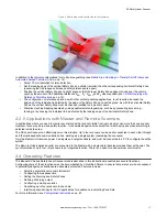
•
In this example, the mobile vehicle is a transfer cart that travels in two directions along a pair of rails. Each direction
of travel is guarded by separate, individually configured Scanners on either end of the vehicle, mounted 150 mm (5.9
inch) above the plane of the floor (not the rails). The plane of the Safety Zone should not exceed 200 mm (7.9 in)
above the floor.
•
In this example, physical damage is not expected because the path of travel is restricted.
•
The typical manufacturing setting is well within the SX's environmental ratings.
•
Safety Zone Length (Minimum Distance D): For this example, assume a maximum vehicle speed of 1200 mm/s (48
in/s), a breaking distance of 900 mm (35 in), SX response time of 122 ms (4 scans), the response time of a vehicle
drive and safety interfacing 100 ms, which results in an overall stopping distance of 1166 mm (46 in). D
SD
= [1200
mm/s × (0.1s + 0.122s)] + 900 mm. This value is added to the Additional Distance Factors (Z) to determine the Safety
Zone length , which for this example are:
◦
Z
SM
= 150 mm (5.9 in)
◦
Z
refl
= 0 — The possibility of retro-reflectors located within the scanning plane of the Protective Field can be
excluded.
◦
Z
F
= 100 mm (4 in) — To the ground clearance of the transfer cart's sides is 60 mm (2.4") and the wheels are
not accessible.
◦
Z
A
= 500 mm (20 in) — The possibility of crushing/trapping hazard against the overhanging conveyor and the
transfer cart is an application specific addition for this example.
◦
The total Safety Zone length (Minimum Distance) from the SX to the leading edge of the Safety Zone is 1916
mm (75.4 in).
•
Safety Zone Width (Additional Side Distance Z): The Z factors to determine the Safety Zone width are primarily the
same as above (Z
SM
= 150 mm, Z
refl
= 0, Z
F
= 100 mm), but the application specific adder, Z
A(SIDE)
, is now used to
account for the entire area to the sides the cart and under the overhang of the conveyor. This distance is 300 mm (12
in); Z
SM
+ Z
F
= 250 mm (9.8 in) , thus Z
A
must equal 50 mm (2 in) to ensure the entire area to the sides of the cart are
monitored. The total width of the Safety Zone for this example is 1666 mm (66 in), which is the width of cart of 1066
mm (42 in) plus the value of the two 300 mm side distances.
•
A 190° Safety/Warning Zone should be used to minimize any unmonitored area at the SX's sides.
•
The vehicle's maximum speed should be identified in the SX's configuration. In this example the maximum speed is
1200 mm/s.
•
The Warning Zone is used to slow the transfer cart and sound a horn if an object is detected.
•
The design of the transfer cart ensures that there are no protruding loads (e.g., pallets) that could become a hazard.
•
The fencing (supplemental safeguarding) along the path of the transfer cart reduces the risk of an individual stepping
directly in front of the cart; this allows the Safety Zone width to be minimized. The fencing also reduces, but does not
eliminate, the possibility of crushing/trapping hazards between the transfer cart and the conveyor because the
individual is detected by the leading edge of the Safety Zone.
•
In this example, the movement of the transfer cart is controlled primarily by on-board logic that is safety-rated. This
allows the movement to begin after the material control system (conveyor logic) commands the cart to a specific
location. Automatic restart function must incorporate a two-second delay after the Safety Zone becomes clear (per
ISO 3691-4).
The on-board logic of the transfer cart that controls beginning and stopping motion and the means of electrical interfacing
must be evaluated during the risk assessment to meet the required level of safety performance (e.g., control reliability or
category 3 or 4).
Vertical Guarding with Reference Point Monitoring
This example application uses two SXs with Safety Zone Switchover to safeguard a pallet load/unload station. The two
Safety Zones per SX are enabled (the red lines) and disabled (pink shaded areas) as pallets are loaded/unloaded and as
they enter/exit the work cell at the rear of the station.
The SX's Area Switch inputs identify the position of a pallet to determine which Safety Zone to disable. The Reference Points
(blue points) ensure that the Safety Zones are in the proper position.
SX Safety Laser Scanner
www.bannerengineering.com - Tel: + 1 888 373 6767
15
Содержание SX5-B
Страница 135: ...Index M mute sensor 69 mute switch 69 ...


