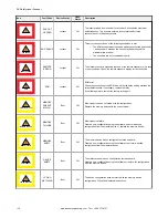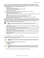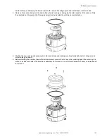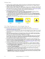
10. After the window passes the first portion of the calibration process, validate the calibration procedure. Test the device
detection capability with a test configuration.
The scanner display will show the
Configuration not Accepted
display icons (white background) and the software
shows the Window Replacement popup window.
11. The test area for the validation procedure is automatically configured. To test the detection capability of the device(s),
use a suitable test piece, e.g. an optically dark, opaque cylinder, with a diameter of 40 mm (like STP-20).
a) Place the test piece on several points at the edges (distance from the device = 1 meter) over the 275° safety
angle. The scanner must detect the test piece at all positions and go to the STOP condition. The number and
location of sites where the test is performed must be chosen so that undetected access to the hazardous area is
not possible. Do not attempt to insert the test piece into dangerous parts of the machine located in the safety
area.
b) Power off the scanner, wait 10 seconds then re-apply power.
c) The scanner remains in test mode until the user validates the test. After the test is validated, select
Test Passed
if the system passed the validation test. After validation, the device switches to online mode with the last
configuration saved before the window replacement. If the validation test failed, select
Test Failed
, and the device
will remain in test mode.
d) If the window calibration fails, the scanner remains in the offline mode until power-off and the software displays an
error message. Repeat the procedure described above. Should the calibration fail again, try a different window or
contact the factory.
12. After the window calibration has successfully completed, click
OK
13. A fault message box displays. If it does not display, click on the red dot in the scanner block. Click
OK
.
14. Re-install the scanner into its original application per the installation sections of the manual. The scanner can operate
in normal operation mode now, but the COMMIT ON FIELD warning message displays at each power-on until a trip
test is performed per the requirements of the installation.
15. Finish the calibration procedure.
a) Connect the scanner to the software (
Scanner
>
Discovery
, then select the scanner).
b) Select
Window Replacement
again.
c) Select
Done
.
After a few seconds, the trip test can be performed.
on p. 65).
If the scanner passes the trip test, it is ready for production.
11.5 Fast Replacement in a System with a Memory Device
Fast replacement allows the user to quickly replace a master scanner, remote scanner, or a memory device after they have
suffered irreparable damage.
CAUTION:
These procedures must be performed by Authorized Personnel only.
These procedures can be performed in the field to restore normal operation and scanner configuration if the replacement
parts have the exact same model number as the scanner being replaced.
Note:
If the replacement scanner has a different model number than the replaced scanner, create a new
configuration using the configuration software.
All instructions are shown on the scanner display and all tasks can be completed using the keypad except when the
instructions refer to the configuration software.
WARNING:
At the end of the Fast Replacement process, the user must confirm the successful completion
of the replacement procedure by checking that the safety conditions have been restored and by validating
the new scanner.
11.5.1 Fast Replacement of a Memory Device
Follow these instructions to replace the Memory Device on an already configured Master unit.
1. Unmount the damaged Memory Device and install the new Memory Device (see
2. The system will first verify that the Memory Device is compatible with the Scanner model (must replace a 8 or 12 pin
QD memory device with an 8 or 12 pin QD memory device or a 17 and 8 pin QD memory device with a 17 and 8 pin
QD memory device). If the Scanner and Memory Device are not compatible, the Scanner display shows the
MEMORY DOESN'T MATCH message.
SX Safety Laser Scanner
www.bannerengineering.com - Tel: + 1 888 373 6767
123
Содержание SX5-B
Страница 135: ...Index M mute sensor 69 mute switch 69 ...


