Banner Engineering Corp.
Vibration Monitoring Solutions Kit Quick Start Guide
Page 11
214301 Rev. C
8.
On the pop-up screen that appears, set up DHCP in one of two ways:
a.
Type in the IP address and network information for a static IP address by selecting the
appropriate fields; or
b.
Toggle from false to true in the field next to
Get an IP address automatically,
then press
OK
.
9.
Push
Link 1
and press on the IP address field. Enter in the IP address of the DXM from earlier and press
OK
.
10.
To finish press
Run
.
Push Information to the Cloud
The DXM Wireless Controller can connect to the Web via Ethernet or an internal cell module. The controller
pushes data from the DXM to the cloud to be stored and displayed on a website. To enable this capability,
modify the DXM’s XML configuration file.
The Banner website for storing and monitoring the system's data is
. Banner Connected
Data Services will automatically generate dashboard icons and graphs for the Solutions Kit that can be placed in
the Dashboard tab. Email alerts can be set up on the Alarms tab as well.
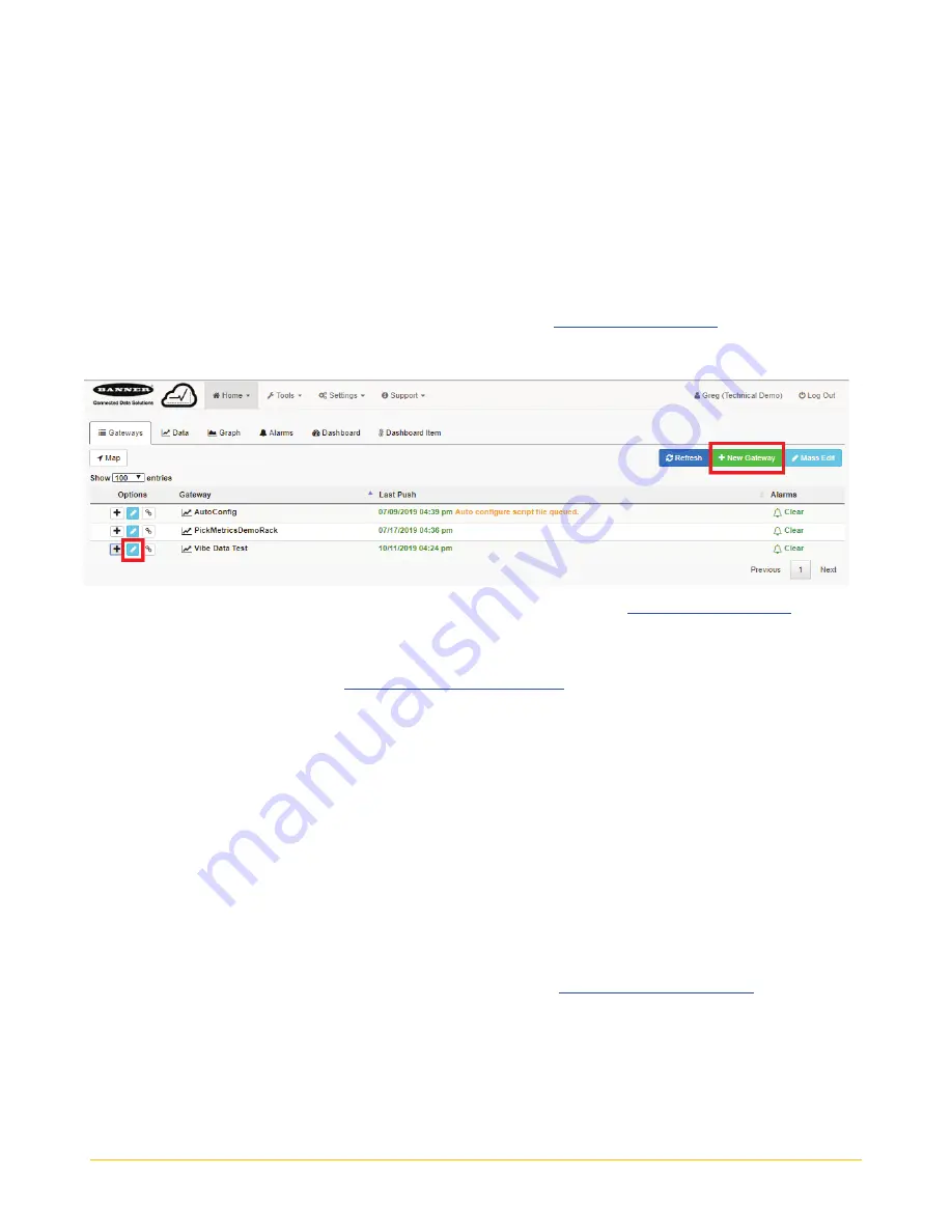
1.
On the Website: Visit the Banner Connected Data Solutions website
(
https://bannercds.com/
)
and log
into an existing account or register a new account.
Click
+ New Gateway.
Name the Gateway then click
Create
.
2.
After the Gateway appears, click the + symbol on the far left and highlight and copy the Gateway ID.
3.
On the computer: Open the
4.
On the DXM: Apply power to the DXM.
5.
Connect the DXM Controller to the computer with a USB cable or skip if the DXM is connected to the
same network as the computer.
6.
Select DXM Model as
DXM700
and connect the DXM to the tool by clicking
Device-> Connection
Settings
in the menu bar.
7.
If you are using the USB cable, select
Serial,
t
hen select the COM port that the USB cable is plugged
into. Click
Connect
. If you are unsure which COM port and multiple appear, attempt to connect to each
one of them until successful. If connected to the same network as the DXM, select
TCP/IP
and enter
the DXM IP address and click
Connect
.
8.
After the DXM is connected to the software, get the current XML file by clicking
Device->Get XML
configuration from
DXM.
Name and save the file to the computer.
9.
Within the tool, click the
Settings
tab on the left and then the
Cloud Services
tab on the top.
10.
Make sure the
Server name/IP
is set to push.bannercds.com.
11.
Select the appropriate
Push interface
to either Cellular or Ethernet. (To set up Ethernet, use the
Network Tab under settings. To set up cellular, refer to the
12.
Leave the
Cloud push interval
and
Sample count
set as they were. The DXM script controls this to
push every 5 minutes.
13.
Registers are preselected to push to the cloud. Some registers can be removed if you are not using all
40 sensors. Additional registers can be added by going to the
Local Registers
tab on the left. The
preselected READ registers are 1-200 for the raw sensor data, 201-240 for vibration failure mask info,
281-320 for sensor connection status, and 5181-5660 for baseline/threshold data. The preselected
READ/WRITE registers are 321-360, which are the re-baselining registers. READ/WRITE is used so the


