•
With the burner turned off from the main switch, connect the
second flame thermostat directly.
•
Open also the gas flow rate regulator integrated in the second
valve so as the necessary output for the main flame is enabled.
•
Now close the main switch to start up the burner.
•
When the burner is lit with the second flame, it is necessary to
check as previously shown, the gas flow and the combustion
with the appropriate instruments.
•
On the basis of checks carried out, change, if necessary, the
gas delivery and the related combustion air in order to adjust
the delivery to the desired value according to specific case (boi
-
ler power).
•
Check the combustion parameters with appropriate instruments
(CO2 MAX=10% O2 MIN= 3% CO MAX=0.1%)
•
Check the efficiency of the safety devices, block devices (by
unplugging the ionisation electrode cable), air pressure switch,
gas pressure switch and thermostats.
IMPORTANT
The pressure switch connection circuit is self controlling.
Therefore, the contact which is meant to be closed in a non
operating state (fan stopped and thus no air pressure in bur
-
ner), should in fact be in this state, otherwise the command/
control equipment will not be switched on (burner remains
inoperative).
•
It must be specified that if the contact is not closed during wor
-
king, the control box will carry out its cycle, but the ignition tran
-
sformer will not be inserted and the gas valves will not open.
Consequently, the burner will go to shut down.
•
Check that the air pressure switch functions properly with bur
-
ner operating, increase the regulating value until it reaches in-
tervention point and the burner should go to shut down.
•
Reset the burner by pressing the appropriate button and rea
-
djust the pressure switch to a value that allows you to detect the
air pressure during the preventilation stage.
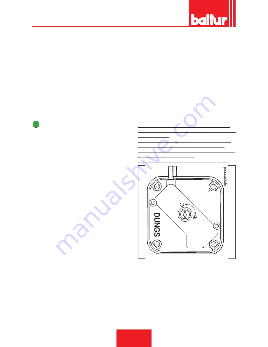
AIR PRESSURE SWITCH
The air pressure switch stops the equipment operation if air pres
-
sure is not at the expected value.
The pressure switch must therefore be adjusted so that it is trigge
-
red to close the NO contact (normally open) when the air pressure
in the burner reaches a particular value.
If the air pressure switch does not detect a pressure greater than
that calibrated, the equipment runs through its cycle but does not
switch on the ignition transformer and does not open the gas val-
ves and so the burner “locks-out”.
To ensure the air pressure switch correct operation, with burner at
the minimum output, increase the adjustment value until reaching
the triggering value which must be followed by the immediate bur
-
ner lock-out.
Release the burner by pressing the appropriate button and rea
-
djust the pressure switch until preventilation air pressure can be
detected.
Air pressure sampling point is upstream the air shutters.
Regulate the air pressure switch after first carrying out all the
other burner adjustments with the air pressure switch adjusted to
the start of the scale.
With the burner operating at a low flow rate (1st flame), slowly
turn the central screw clockwise until the burner locks out.
Then give the screw a half-turn anti-clockwise and repeat burner
start-up to check for proper operation.
If the burner locks out again give the screw another half-turn.
ENGLISH
14 / 30
0006080763_201611
Содержание BTG 3,6P
Страница 2: ......
Страница 31: ...SCHEMI ELETTRICI ITALIANO 29 30 0006080763_201611...
Страница 61: ...WIRING DIAGRAMS ENGLISH 29 30 0006080763_201611...
Страница 63: ......


