ENGLISH
24 / 42
0006160060_201802
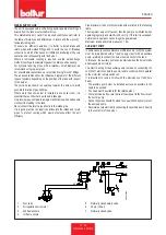
• The control pressure switches for the gas (minimum) are to prevent
the working of the burner when the pressure of the gas is not as
provided for. The minimum pressure switch must use the contact
that is closed when the pressure switch detects a pressure higher
than the value it is set to. The minimum pressure switch regulation
must be done upon burner start-up according to the pressure
detected each time. The triggering (opening of the circuit) of any
of the pressure switches when the burner is running (flame on)
causes the burner to stop immediately. Upon first ignition of the
burner, it is essential to check that it works properly.
DANGER / CAUTION
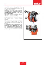
Once the adjusting operations are completed, visually check
that the thin plate on which the bearing acts has a progressive
profile. Also check trough the dedicated tools that during the
passage between first and second stage the combustion
parameters do not excessively vary from the optimal values.
DANGER / CAUTION
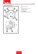
If burner has to be used with LPG, we recommend working
on gas-side tie rod by loosening the two terminals so as to
increase tie rod length by 5mm.
acc_reg001.psd
12
13
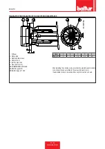
UV PHOTOCELL
Even the slightest greasiness will compromise the passage of the
ultraviolet rays through the UV photocell bulb, thus preventing the
sensitive internal element from receiving the quantity of radiation
necessary for it to work properly. If the bulb is fouled with diesel, fuel
oil, etc... it must be properly cleaned.
CAUTION / WARNING
Even by simply touching the bulb with fingers, it is possible
to leave a slight greasiness which could compromise UV
photocell operation.
The UV photocell does not detect daylight or the light from a common
lamp. Sensitivity can be checked with a flame (cigarette lighter, candle)
or with the electric discharge between the electrodes of a common
ignition transformer. To ensure proper operation, the UV photocell
current value should be sufficiently stable and should not drop below
the minimum value required by the specific equipment; this value is
indicated in the wiring diagram. It may be necessary to search for the
best position by sliding (axial or rotational movement) the casing that
contains the photocell with respect to the fastening clamp. This can
be checked by connecting a micro-ammeter, with a suitable scale, in
series to one of the two UV photocell connection cables. Obviously
the + and - polarity must be respected. The equipment ...needs a
photocell current between 200 and 500 microA.
CONTROLS
• After starting up the burner, check the safety devices (flame
detector, lock-out system, thermostats)
• The flame control device should trip if the flame extinguishes
during operation (this check should be made after at least 1 minute
after ignition)
• The burner should be able to lock out and remain locked when,
during the ignition sequence in the time pre-set by the control box,
the flame does not regularly appear. The lock-out causes the
immediate stop of the motor and burner and the switching on of the
corresponding lock-out light indication. To check the efficiency of
the flame detector and lock-out system, proceed as follows:
Содержание 56470010
Страница 2: ......
Страница 4: ...ITALIANO 2 42 0006160060_201802 ITALIANO Schemi elettrici 41 ...
Страница 43: ...ITALIANO 41 42 0006160060_201802 SCHEMI ELETTRICI ...
Страница 46: ...ENGLISH 2 42 0006160060_201802 ENGLISH Wiring diagrams 41 ...
Страница 85: ...ENGLISH 41 42 0006160060_201802 WIRING DIAGRAMS ...
Страница 87: ......


