Maintenance
Procedures
(continued)
9
As an option, an electric water level control package is
available in lieu of the above described mechanical make-
up assembly. The package consists of a probe-type liquid
level control assembly and a slow closing solenoid valve.
Stainless steel electrodes, factory set at predetermined
lengths, extend from a NEMA 4 electrode holder into the
cold water basin. These electrodes should be periodi-
cally wiped clean to prevent accumulations of scale,
corrosion, sludge or biological growth from interfer-
ing with the electrical circuit. With the electric water
level control package, the water level is maintained at the
recommended operating level regardless of the system
thermal load. Therefore, it is not necessary, nor is it rec-
ommended that the operating level be adjusted. During
initial and seasonal start-up, the probe-type level control
assembly should be bypassed to fill the cold water basin
to approximately 1/2” below the overflow connection.
Unit operation at the recommended water level will
ensure that the unit basin contains sufficient water volume
to prevent air entrainment in the circulating pump during
system start-up and to provide sufficient excess basin
capacity to accept the total system pull-down volume. The
“total system pull-down volume” is the quantity of water
suspended in the tower during pump operation plus that
contained in the water distribution system, external piping,
and any heat exchangers which could drain to the tower
cold water basin when the circulating pump is shut down.
FAN SHAFT BEARINGS
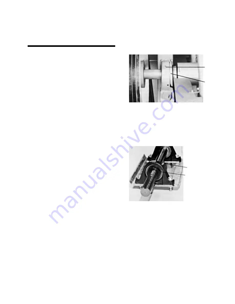
The fan shafts on VTO, VT1, VTL, VF1, VFL, VC1, and
VCL units are supported at each end by ball bearings (see
Figure 2), each equipped with a lubrication fitting and
locking collar. Models VTO-65 to 116, VF1-027, VF1-036,
and VC1-72 thru 135 also have a sleeve bearing (see
Figure 3) located midway on the shaft.
The fan shafts on VC2 units are supported by ball bear-
ings (see Figure 2A) in the middle of the shaft with fans at
each end. Each bearing is equipped with a lubrication fit-
ting and locking collar. Lubrication lines are extended to
the outside of the unit as standard.
Ball Bearings
Under normal operating conditions, the bearings should
be greased every 2,000 operating hours or at least every
six months. The bearings should also be greased at sea-
sonal start-up and shut-down. Only lubricate the bearings
with one of the following water resistant inhibited greases
which are good for ambient temperatures ranging from
–65°F to 250°F:
American – Rycon Premium #3
Exxon – Beacon #325
Shell – Aeroshell #7
Mobil – Mobilgrease #28
Chevron – SRI #3
Keystone – 84 EP Light
Only lubricate the bearings with a hand grease gun.
Do not use high pressure grease guns since they may
rupture the bearing seals. When lubricating, purge the
old grease from the bearing by gradually adding grease
until a bead of new grease appears at the seal.
Sleeve Bearings
Prior to start-up and during the first week of operation, the
bearing oil cup must be refilled with an industrial-type min-
eral oil (see Table 3) to saturate the felt wick in the bear-
ing reservoir. After the initial start-up, fill the bearing oil
cup every 1,000 operating hours or at least every six
months. When ambient temperatures below 0°F are
expected, a light oil must be used. With such light oils, the
bearing oil cup should be checked and refilled several
times during the first several hours of operation until the
bearings reach operating temperature.
LUBE
FITTING
LOCKING
COLLAR
Figure 2 – Ball Bearing
LUBE FITTING
LOCKING COLLAR
Figure 2A – Ball Bearing


