background image

80

deutsch

6


Sekundäre Gerätefunktionen (Fortsetzung)

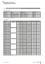
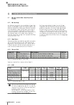
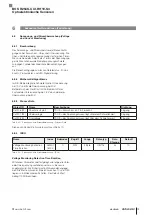
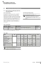
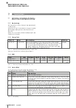
6.12.2  Mathematik/Algorithmus

Die Neigungsabweichung wird weder mit der horizontalen 

Ebene noch mit dem vertikalen Gravitationsfeld verglichen, 

sondern mit der eingelernten Orientierung.
Zusammengefasst dargestellt:
–  Neigungsabweichung = absoluter Wert von (Referenz 

eingelernter Orientierung – tatsächliche Orientierung)

–  Werte: 0…180

–  Einheit: Grad (°)

6.12.3  Process Data

Object ID

Name

Beschreibung

Richtung

0x0036 (54)

Inclination Deviation Value

1)

Wert der Neigungsabweichung

Eingang

0x0037 (55)

Inclination Alarm Status

Neigungsalarm-Status

Eingang

1)

 Unit = ° (degree)

Tab. 6-55:  Neigungsdetektion und Einstellhilfe – Process Data

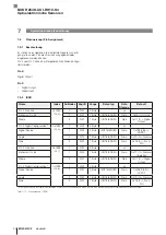
6.12.4  ISDU

Name

Index

Subindex

Zugriff

Länge

Datentyp

Data 

Storage

Default

Inclination Alarm Configuration

0x2151 

(8529)

0

R/W

2 Byte

Ja

Inclination Alarm Enable

1

R/W

1 Byte

BOOL

Nein

0x00 (0)

Inclination Alarm Threshold

2

R/W

1 Byte

UINT8

Nein

0x0A (10)

Inclination Alarm Status

0x2152 

(8530)

0

R

2 Byte

n/a

Inclination Alarm Teaching Status

1

R

1 Byte

BOOL

n/a

Inclination Alarm Status

2

R

1 Byte

BOOL

n/a

Reference Taught Position

0x2153 

(8531)

0

R

12 Byte

n/a

X Reference Value

1

R

4 Byte

FLOAT32

n/a

Y Reference Value

2

R

4 Byte

FLOAT32

n/a

Z Reference Value

3

R

4 Byte

FLOAT32

n/a

Inclination Deviation Value

0x2154 

(8532)

0

R

1 Byte

UINT8

n/a

Tab. 6-56:  Neigungsdetektion und Einstellhilfe – ISDU

BOS R254K-UUI-RH10-S4

Optoelektronische Sensoren

Содержание BOS R254K-UUI-RH10-S4

Страница 1: ...deutsch Konfigurationsanleitung english Configuration Guide BOS R254K UUI RH10 S4...

Страница 2: ...www balluff com...

Страница 3: ...BOS R254K UUI RH10 S4 Konfigurationsanleitung deutsch...

Страница 4: ...www balluff com...

Страница 5: ...Switching Profiles 32 5 5 Transmitter Lebenszeit Information Transmitter Lifetime Info 42 5 6 Sensor Betriebsarten Sensor Operating Modes 44 5 7 Signalqualit t Signal Quality 45 6 Sekund re Ger tefun...

Страница 6: ...ration Variant Configuration 93 7 5 Pinzuweisung Pin Assignment 94 7 6 Bedeutung der LED Zust nde und Konfiguration LED Meaning and Configuration 97 7 7 Prozessdateninformation und konfiguration Proce...

Страница 7: ...Verwendete Symbole und Konventionen Einzelne Handlungsanweisungen werden durch ein vorangestelltes Dreieck angezeigt Handlungsanweisung 1 Zahlen ohne weitere Kennzeichnung sind Dezimalzahlen z B 23 He...

Страница 8: ...4 auf Seite 28 beschrieben 2 Basiswissen IO Link 2 5 Prozessdatenstrom Die Daten bertragung basiert auf der allgemeinen Profil spezifikation IO Link Common Profile 1 0 Beispiel siehe Bild 2 1 Bild 2 1...

Страница 9: ...ndo abgeschlossen Da die Pr fung der Daten erst zum Ende der Parametrie rung erfolgt k nnen auch voneinander abh ngige Daten problemlos eingestellt werden 2 8 Data Storage Data Storage bezeichnet ein...

Страница 10: ...ersicht siehe Kapitel 3 4 auf Seite 16 und in den einzelnen Funktionsbeschreibungen zu finden Die Resetbefehle Reset Commands sind auf Seite 92 beschrieben 2 11 Device Funktionen und Master Gateway Di...

Страница 11: ...urrent Monitoring siehe Seite 73 Status extremer Umweltbedingung Extreme Environ ment Status siehe Seite 75 Interne Temperatur Internal Temperature siehe Seite 77 Neigungsdetektion und Einstellhilfe I...

Страница 12: ...ab 3 1 Ger tevarianten 3 3 Prozessdatenprofile Die Einstellung des Prozessdatenprofils ist in Kapitel 7 7 Prozessdateninformation und konfiguration Process Data Info and Configuration beschrieben 3 3...

Страница 13: ...5 Bit 7 MSB Bit 6 Bit 5 Bit 4 Bit 3 Bit 2 Bit 1 Bit 0 LSB Reserved Byte 6 Bit 7 MSB Bit 6 Bit 5 Bit 4 Bit 3 Bit 2 Bit 1 Bit 0 LSB Current Signal Quality Byte 7 Byte 8 Bit 7 MSB Bit 6 Bit 5 Bit 4 Bit 3...

Страница 14: ...15 Bit 7 MSB Bit 6 Bit 5 Bit 4 Bit 3 Bit 2 Bit 1 Bit 0 Bit 7 Bit 6 Bit 5 Bit 4 Bit 3 Bit 2 Bit 1 Bit 0 LSB Transducer Signal Byte 16 Bit 7 Bit 6 Bit 5 Bit 4 Bit 3 Bit 2 Bit 1 Bit 0 System Error Reserv...

Страница 15: ...t 2 Bit 1 Bit 0 Reserved Reserved Switching Speed too high Switching Speed too low Switching Speed ok Switching Counter Limit exceeded Switching Counter Limit reached Switching Counter Limit not reach...

Страница 16: ...t 5 Bit 4 Bit 3 Bit 2 Bit 1 Bit 0 LSB Reserved Byte 6 Bit 7 MSB Bit 6 Bit 5 Bit 4 Bit 3 Bit 2 Bit 1 Bit 0 LSB Current Signal Quality Byte 7 Byte 8 Bit 7 MSB Bit 6 Bit 5 Bit 4 Bit 3 Bit 2 Bit 1 Bit 0 B...

Страница 17: ...it 5 Bit 4 Bit 3 Bit 2 Bit 1 Bit 0 System Error Signal Quality Bad Reserved Temperature Status 1 Inclination Alarm Vibration Alarm Humidity Bad 1 Object ID 0x004E Temperature exceeded Custom Threshold...

Страница 18: ...STRING n a Application Specific Tag 0x0018 24 0 R W 32 Byte STRING Ja Function Tag 0x0019 25 0 R W 32 Byte STRING Ja Location Tag 0x001A 26 0 R W 32 Byte STRING Ja Product Type Code 0x0700 1792 0 R 6...

Страница 19: ...sis 3 R W 2 Byte INT16 Nein 0x0005 5 SSC 3 Parameter 0x4000 16384 0 R W 8 Byte Nein Setpoint 1 1 R W 4 Byte INT32 Nein 0x000003E8 1000 Setpoint 2 2 R W 4 Byte INT32 Nein 0x7FFFFFFC deaktiviert SSC 3 C...

Страница 20: ...l 1 1 R W 1 Byte UINT8 ENUM Nein 0 Channel 2 2 R W 1 Byte UINT8 ENUM Nein 0 Channel 3 3 R W 1 Byte UINT8 ENUM Nein 0 Channel 4 4 R W 1 Byte UINT8 ENUM Nein 0 Signal Delay On Delay 0x0098 152 0 R W 8 B...

Страница 21: ...yte UINT8 ENUM Nein 0 Limit 3 R W 2 Byte UINT16 Nein 2 Startup Delay 4 R W 1 Byte UINT8 Nein 0 Switching Counter Status 0x00B7 183 0 R 3 Byte n a State 1 R 1 Byte UINT8 ENUM n a Value 2 R 2 Byte UINT1...

Страница 22: ...Byte Ja Logic Block 1 Input 3 1 R W 2 Byte UINT16 Nein 0 Logic Block 2 Input 3 2 R W 2 Byte UINT16 Nein 0 Logic Block 3 Input 3 3 R W 2 Byte UINT16 Nein 0 Logic Block 4 Input 3 4 R W 2 Byte UINT16 Ne...

Страница 23: ...R W 2 Byte INT16 Nein 0xFFF6 10 Lifetime Extreme Status 0x00D1 209 0 R 5 Byte n a State 1 R 1 Byte UINT8 ENUM n a Time 2 R 4 Byte UINT32 n a Interne Temperatur Device Temperature 0x0052 82 0 R 10 Byte...

Страница 24: ...AT32 n a Inclination Deviation Value 0x2154 8532 0 R 1 Byte UINT8 n a Vibrationsdetektion Vibration Level 0x210E 8462 0 R 4 Byte FLOAT32 n a Vibration Alarm Confi guration 0x210F 8463 0 R W 5 Byte Ja...

Страница 25: ...ink Mode 2 R W 1 Byte UINT8 ENUM Nein 0x01 1 Digital Output Pin 4 Digital Configuration 0x0091 145 0 R W 4 Byte Ja Signal Source 1 R W 2 Byte UINT16 ENUM Nein 0x0038 56 ADSS1 Logic 2 R W 1 Byte UINT8...

Страница 26: ...nl nge UINT8 n a Last Valid Process Data Inputs 0x0028 40 0 R Variante 1 2 1 Byte Variante 3 17 Byte Variante 4 6 Byte Variante 5 17 Byte n a Last Valid Process Data Outputs 0x0029 41 0 R 1 Byte n a P...

Страница 27: ...e Reset Device Reset bedeutet einen Warmstart des Ger ts Dabei werden der Microcon troller neu hochgefahren und alle Initialisierungen neu durchgef hrt ohne dass eine nderung der Parameterwerte erfolg...

Страница 28: ...cification 0x5111 20753 Warnung Unterschreitung der prim ren Versorgungsspannung Abweichungen in der Versorgung pr fen 2 Out of Specification 0x8CD0 36048 Warnung Neigungsalarm Installation pr fen 1 M...

Страница 29: ...nicht mehr gew hrleistet dient nur zur Information 0 Device is operating properly 0x8D23 36131 Fehler Schreibzyklenlimit erreicht Speichern nicht mehr gew hrleistet Austausch empfohlen 1 Maintenance...

Страница 30: ...den siehe Tab 4 2 auf Seite 28 Folgende Ger tevarianten sind w hlbar siehe auch Kapi tel 7 4 auf Seite 93 Varianten name Ger teken nung ber tragungsrate Minimale Zyklus zeit Device Frame Spezifikation...

Страница 31: ...BOS R254K UUI RH10 S4 ADSS Product Order Code 0x0701 1793 0 R 7 Byte STRING Nein BOS02C3 Tab 5 1 Identifikation ISDU Application Specific Tag Mit dem Parameter Application Specific Tag kann ein Strin...

Страница 32: ...g ISDU Device Discovery Timeout Der Parameter Device Discovery Timout stellt die Zeitdauer des Device Discovery Signals ein das ber LEDs ange zeigt wird Der Wert wird in Minuten angegeben Es ist der W...

Страница 33: ...bject ID Name Beschreibung Richtung 0xFFF7 65527 Transducer Value Ermittelter Messwert Eingang Tab 5 4 Optisches Frontend Process Data 5 3 4 ISDU Name Index Subindex Zugriff L nge Datentyp Data Storag...

Страница 34: ...ere Messgrenze 1000 0x03E8 Messbereich obere Messgrenze 4000 0x0FA0 Tab 5 7 Schaltprofile Schaltpunktauswertung deaktivieren bersicht AdSS Profil Nur ein Schaltkanal Switching Signal Channel SSC verf...

Страница 35: ...erhalten Messwert Schaltpunkt 1 Ausgang aktiv Messwert Schaltpunkt 2 Ausgang inaktiv Bild 5 5 High SP1 SP2 Low Messwert Schaltausgang Zweitpunktmodus 5 Prim re Ger tefunktionen Fortsetzung Window Mode...

Страница 36: ...flow 1 Teach SP1 Messwert Schaltausgang Single Value Teach im Single Point Mode Bild 5 8 High SP1 SP2 Low Workflow 1 Teach SP2 2 Teach SP1 Messwert Schaltausgang Single Value Teach im Two Point Mode 5...

Страница 37: ...each SP1 Stop 3 Dynamic Teach SP2 Start 4 Dynamic Teach SP2 Stop erfasste Messwerte Mess wert Schaltausgang Dynamic Teach im Two Point Mode Dynamic Teach Balluff Spec Dieses Teach Verfahren ist nur im...

Страница 38: ...e der neue Setpoint wird als Schaltpunkt in Verbindung mit der Standardhysterese verwendet Die bisherige Konfiguration wird verworfen Blinkt die LED f r 3 Sekunden wurde der Teachvorgang nicht erfolgr...

Страница 39: ...le Process Data 5 4 4 ISDU AdSS Name Index Subindex Zugriff L nge Datentyp Data Storage Default SSC Parameter SP 0x0038 56 0 RW 16 Bit IntT16 Nein 0x03E8 1000 SSC Configuration Logic 0x0039 57 0 RW 8...

Страница 40: ...eachpoint nicht erfasst oder nicht erfolgreich erfasst 1 Teachpoint erfolgreich erfasst 4 Flag SP TP1 3 0 State 0 IDLE Kein aktuell aktiver Teachvorgang 1 SUCCESS Letzter Vorgang war erfolgreich 2 Res...

Страница 41: ...int Logic 1 R W 1 Byte UINT8 Nein 0x00 Switchpoint Mode 2 R W 1 Byte UINT8 Nein 0x01 Switchpoint Hysteresis 3 R W 2 Byte INT16 Nein 0x0005 5 SSC 3 Parameter 0x4000 16384 0 R W 8 Byte Nein Setpoint 1 1...

Страница 42: ...rt Ist ein Setpoint deaktiviert ist dieser auf den Wert 0x7FFC AdSS oder 0x7FFFFFFC LSSC No Measurement Data eingestellt und der Wert kann auch nicht ge ndert werden Ferner ist es m glich ber diesen W...

Страница 43: ...Setpoint 21 0x47 71 Teach SP1 Start Startet dyna misches Teach in f r Setpoint 1 0x48 72 Teach SP1 Stop Stoppt dyna misches Teach In f r Setpoint 1 und berechne den Schaltpunkt 0x49 73 Teach SP2 Start...

Страница 44: ...5 22 Transmitter Lebenszeit Information ISDU Transmitter Lifetime Transmitter Lifetime zeigt den aktuellen Status Wert Name Beschreibung 0x01 1 Green Es sind keine Einschr nkungen in der Sensorfunkti...

Страница 45: ...s Event Code Event Typ Beschreibung Device Status 0x1860 6240 Warnung Warnung zur Lebensdauer des Senders Sensor bei n chstem Wartungszyklus aus tauschen 1 Maintenance Required Tab 5 24 Transmitter Le...

Страница 46: ...pr zise Erfassung von Objek ten Durch eine Erh hung der Mehrfachauswertung des Schaltpunkts l sst sich der Sensor durch externe St rungen weniger beeinflussen als im Standard Mode Die aktive Unterdr c...

Страница 47: ...lqualit t unter einen einstellbaren Schwellenwert f llt und gibt Entwar nung wenn wieder ein zufriedenstellendes Niveau der Signalqualit t erreicht wird Der Signalzustand wird auch durch eine orange L...

Страница 48: ...als boolescher Wert angezeigt Wenn der Wert TRUE ist liegt die Signalqualit t unter dem Schwellenwert wenn der Wert FALSE ist ist die Signalqualit t gleich oder ber dem Schwellenwert Dieser Status wi...

Страница 49: ...Byte UINT8 ENUM Ja 0 Tab 6 1 Externe Signalausblendung ISDU External Signal Blanking ber den Parameter External Signal Blanking kann die Funktion aktiviert und deaktiviert werden Wert Bedeutung Beschr...

Страница 50: ...alverz gerung Mathematik Algorithmus 6 2 3 Process Data Object ID Name Beschreibung Richtung 0x0008 8 Signal Delay Channel 1 Ausgangssignal Signal Delay Channel 1 Eingang 0x0009 9 Signal Delay Channel...

Страница 51: ...in 0 Channel 4 4 R W 1 Byte UINT8 ENUM Nein 0 Signal Delay On Delay 0x0098 152 0 R W 8 Byte Ja Channel 1 1 R W 2 Byte UINT16 Nein 0 Channel 2 2 R W 2 Byte UINT16 Nein 0 Channel 3 3 R W 2 Byte UINT16 N...

Страница 52: ...Input Signal Delay Mode Mit Signal Delay Mode kann der aktuelle Modus der Sig nalverz gerungsfunktion ausgew hlt werden Wert Bedeutung Beschreibung 0x00 0 Deactivated deaktiviert 0x01 1 Delay On Off u...

Страница 53: ...Restore Factory Settings Setzt beschreibbare Parameter auf den Default Wert zur ck Tab 6 9 Signalverz gerung System Commands F r eine bersicht aller System Commands siehe Kapi tel 3 5 auf Seite 25 6...

Страница 54: ...eschreibung Richtung 0x0010 16 Switching Speed ok Switching Speed Value innerhalb der Grenzen Eingang 0x0011 17 Switching Speed too low Switching Speed Value unterhalb der Grenze Eingang 0x0012 18 Swi...

Страница 55: ...Byte UINT16 Nein 100 Speed Upper Limit Low 4 R W 2 Byte UINT16 Nein 85 Speed Lower Limit High 5 R W 2 Byte UINT16 Nein 65 Speed Lower Limit Low 6 R W 2 Byte UINT16 Nein 50 Startup Delay 7 R W 1 Byte U...

Страница 56: ...66 102 Logicblock Result 4 Tab 6 12 Signalgeschwindigkeits berwachung Switching Speed Monitoring Input 6 Sekund re Ger tefunktionen Fortsetzung Switching Speed Monitoring Mode Mit Switching Speed Moni...

Страница 57: ...nd Wert Ger teaktion 0x81 129 Application Reset Setzt beschreibbare Parameter auf den Default Wert zur ck 0x82 130 Restore Factory Settings Setzt beschreibbare Parameter auf den Default Wert zur ck 0x...

Страница 58: ...als die konfigurierte Z hlergrenze wird das Z hlerzustandsflag not reached gesetzt Sobald der Z hlwert gr er oder gleich der konfigurierten Z hler grenze ist wird das Z hlerzustandsflag reached geset...

Страница 59: ...ert eins Der Z hlwert kann jederzeit durch ein System Command zur ckgesetzt werden Z hlwert Null Bild 6 4 Schaltz hler Auto Mode 6 4 3 Process Data Object ID Name Beschreibung Richtung 0x0003 3 Switch...

Страница 60: ...16 ENUM Nein 0 Mode 2 R W 1 Byte UINT8 ENUM Nein 0 Limit 3 R W 2 Byte UINT16 Nein 2 Startup Delay 4 R W 1 Byte UINT8 Nein 0 Switching Counter Status 0x00B7 183 0 R 3 Byte Nein State 1 R 1 Byte UINT8 E...

Страница 61: ...haltz hler Switching Counter Input 6 Sekund re Ger tefunktionen Fortsetzung Switching Counter Mode Mit Switching Counter Mode kann der aktuelle Modus der Z hlfunktion ausgew hlt werden Wert Bedeutung...

Страница 62: ...0 Restore Factory Settings Setzt beschreibbare Parameter auf den Default Wert zur ck 0xA6 166 Switching Counter Reset Setzt Z hler wert und Flags zur ck Tab 6 22 Schaltz hler System Commands F r eine...

Страница 63: ...Durchschnitt Eingang Maximum Minimum Berechnung von Minimum Maximum und Durchschnitt Wie in Bild 6 5 dargestellt wird die Berechnung durch den Startbefehl eingeleitet und durch den Stoppbefehl gestop...

Страница 64: ...breite 9 Wert periodisches Fenster Periodischer Fensteransatz Beispiel 6 5 3 Process Data Object ID Name Beschreibung Richtung 0x0053 83 Minimum Minimalwert Eingang 0x0054 84 Maximum Maximalwert Einga...

Страница 65: ...e 3 R 4 Byte FLOAT32 n a Moving Average 4 R 4 Byte FLOAT32 n a Number of samples 5 R 4 Byte UINT32 n a Status 6 R 1 Byte UINT8 n a Tab 6 24 Grundlegende Statistik ISDU Statistics Data Configuration In...

Страница 66: ...age Window Unit Statistics Data Configuration Moving Average Window Value Der Wert f r den gleitenden Durchschnitt moving average window muss im Wertebereich liegen siehe Tab 6 28 Um den gleitenden Du...

Страница 67: ...5 5 System Commands Command Wert Ger teaktion 0xA7 167 Statistics Reset Setzt alle Aus gangsparameter auf 0 und alle Benutzereinstellungen auf die Default Werte zur ck 0xA8 168 Statistics Start Min Ma...

Страница 68: ...eit berschreitung der Minimalwert Maximalwert Durchschnitt Berechnung Es meldet keine Zeit berschreitung f r die Berechnung des gleitenden Durchschnitts da sich der Zeitablauf des gleitenden Durchschn...

Страница 69: ...gestellt wer den Obwohl jeder Logikblock 4 Eing nge unterst tzt kann ein Block mit weniger Eing ngen verwendet werden Die nicht verwendeten Eing nge werden so eingestellt dass sie das Ergebnis nicht b...

Страница 70: ...Subindex 4 INPUTS Logik Block 4 RESULT Index 0x77 Subindex 3 Index 0x77 Subindex 4 Index 0x7A Subindex 3 Index 0x7A Subindex 4 Index 0x78 Subindex 3 Index 0x78 Subindex 4 Index 0x79 Subindex 3 Index...

Страница 71: ...Byte UINT16 Nein 0 Logic Block Input 2 0x0077 119 0 R W 8 Byte Ja Logic Block 1 Input 2 1 R W 2 Byte UINT16 Nein 0 Logic Block 2 Input 2 2 R W 2 Byte UINT16 Nein 0 Logic Block 3 Input 2 3 R W 2 Byte...

Страница 72: ...innend mit einer Speicherung nach 1 Minute danach 2 Minuten danach 4 Minuten danach 8 Minuten bis zu einem maximalen Speicherintervall von 12 Minuten 6 7 3 Process Data Object ID Name Beschreibung Ric...

Страница 73: ...erintervall nach jedem Speichervorgang Dies ist auf ein Speicherintervall von 12 Minuten begrenzt Die Intervalle betragen 1 2 4 8 12 Minuten 0x01 1 Static Betriebsstundenz hler werden alle 12 Minuten...

Страница 74: ...Counter 0x0058 88 0 R 8 Byte n a Boot Cycle Counter 1 R 4 Byte UINT32 n a Custom Boot Cycle Counter 2 R 4 Byte UINT32 n a Tab 6 41 Betriebsstartz hler ISDU Boot Cycle Counter Dieser Parameter speiche...

Страница 75: ...ng bei 30 V 6 9 3 Process Data Object ID Name Beschreibung Richtung 0x0016 22 Short circuit pin 2 TRUE Kurzschluss an Pin 2 erkannt Eingang 0x0017 23 Undervoltage TRUE das Spannungsniveau liegt unter...

Страница 76: ...berwachung System Com mands F r eine bersicht aller System Commands siehe Kapi tel 3 5 auf Seite 25 6 9 6 Events Event Code Event Typ Beschreibung Device Status 0x5110 20752 Warnung berschreitung der...

Страница 77: ...nnungsversorgung w hrend einer Extrembedingung unterbrochen kann der Zeitz hler einen Fehler von maximal 180 Sekunden haben 6 10 3 Process Data Object ID Name Beschreibung Richtung 0x0041 65 Lifetime...

Страница 78: ...r Time kann die zusammengefasste Zeit in Sekunden in der sich das Ger t in einer Extrembedingung befunden hat ausgelesen werden 6 10 5 System Commands Command Wert Ger teaktion 0x81 129 Application Re...

Страница 79: ...80 Device Temperature Aktuelle Ger tetemperatur in C Ausgang 0x004E 78 Temperature Status Customer Limits Ger tetemperatur au erhalb des eingestellten Temperaturbereichs Ausgang 0x004F 79 Temperature...

Страница 80: ...er t wird au er halb der ger tespezifischen Temperaturgrenzen betrie ben Gefahr von Ger tesch den 4 Failure 0x4210 16912 Warnung Device temperature overrun Clear Heat Of Source Gefahr von Ger teschade...

Страница 81: ...te 1 Sekunde Mit der Neigungsdetektion kann erkannt werden ob das Ger t seine urspr ngliche Einbauposition ge ndert hat und so z B eine m gliche Dejustage und daraus resultierende Fehlfunktionen fr hz...

Страница 82: ...Tab 6 55 Neigungsdetektion und Einstellhilfe Process Data 6 12 4 ISDU Name Index Subindex Zugriff L nge Datentyp Data Storage Default Inclination Alarm Configuration 0x2151 8529 0 R W 2 Byte Ja Incli...

Страница 83: ...festlegen verwenden Das Device kann die Neigung erst berechnen wenn die Referenzposition eingelernt ist Alarm Inclination Status Bit Description 0 Device ist in seiner eingelernten Position Orientie r...

Страница 84: ...gt dass das Ger t seine urspr ngliche Position Schwellenwert ber cksichtigen verloren hat Die Befestigung des Ger ts sollte berpr ft werden Das Device ist noch funktionsf hig aber die gemessenen Werte...

Страница 85: ...sbarer Bereich der Schwingungs beschleunigung 0 16 g Messfehler 10 1 Der Schwinggeschwindigkeitsbereich ist frequenzabh ngig Der angegebene Wert ist das theoretische Maximum innerhalb dieses Frequenzb...

Страница 86: ...berwachungsfunktionalit t bietet wobei die Zustands berwachung die prim re Funktion des Sensors ist und dieser am Objekt oder an der Maschine montiert wird Bild 6 11 Trendanalyse 6 13 3 Process Data...

Страница 87: ...Alarm aktiviert Ziel Entprellung und Vermeidung von Sto werten Einheit mm s Minimalwert 0 0 Maximalwert 1770 0 Vibration Alarm Status Das Status Flag ist TRUE wenn die Vibration den Alarm schwellenwe...

Страница 88: ...gang Tab 6 66 Feuchtigkeitsdetektion Process Data Siehe auch Kapitel Prozessdatenprofile auf Seite 10 6 14 3 ISDU Name Index Subindex Zugriff L nge Datentyp Data Storage Default Humidity 0x005C 92 0 R...

Страница 89: ...nterschiedliche Zugriffs und Verwendungszwecke gespeichert Da die Anzahl an Schreibzyklen im Permanentspeicher begrenzt ist wird die Anzahl in jedem Abschnitt mit einem Z hler berwacht Alle Datenabsch...

Страница 90: ...atus und detailierter Ger testatus ISDU 7 1 4 Device Status Der Zugriff auf den Parameter erfolgt ber Subindex 0 Die ausgegebenen Werte sind wie folgt zu interpretieren Wert Status Beschreibung 0 Devi...

Страница 91: ...Eintrag in der Liste besteht aus dem EventQualifier und dem EventCode und hat eine Datenl nge von 3 Byte Die gesamte Liste kann ber Subindex 0 abgefragt werden einzelne Eintr ge mit dem jeweiligen Su...

Страница 92: ...in 0 Event Code Suppression Teach in 0x0072 114 0 W 2 Byte UINT16 n a Event Code Suppression Delete 0x0073 115 0 W 2 Byte UINT16 n a Tab 7 5 Diagnoseunterdr ckung ISDU 7 2 3 Diagnosis Level Configurat...

Страница 93: ...rt und wird als FREE interpretiert Jede Event Meldung ist wie folgt aufgebaut Byte1 MSB sent first Byte0 LSB Event Code High Byte Event Code Low Byte Tab 7 7 Diagnoseunterdr ckung Event Message Suppre...

Страница 94: ...1 2 durchgef hrt R cksetzen aller Parameter und Ger teeinstellungen auf Standardwerte mit Ausnahme der Identifikations und Tagging Parameter Keine R cksetzung der Konfiguration der Ger tevariante DS U...

Страница 95: ...Ger tevariante l sst sich entweder durch diesen Parameter umstellen oder durch Verwendung des IO Link Kompatibit tsmodus Wenn dieser Parameter beschrieben wird wird nicht sofort die Ger tevariante ge...

Страница 96: ...te Ja Signal Source 1 R W 2 Byte UINT16 ENUM Nein 0x0038 56 ADSS1 Logic 2 R W 1 Byte UINT8 ENUM Nein 0x00 0 Normal Type 3 R W 1 Byte UINT8 ENUM Nein 0x02 2 Push Pull Pin 2 Function 0x0093 147 0 R W 2...

Страница 97: ...lt werden Es stehen verschiedene Signalquellen zur Verf gung die auf einem Pin ausgegeben oder einge lesen werden k nnen Wert Name Digital Output 0x0003 3 Switching Counter Limit Not Reached 0x0004 4...

Страница 98: ...Name Beschreibung 0x00 0 Normal Nicht Invertierende Logik 0x01 1 Inverted Invertierende Logik Tab 7 16 Pinzuweisung Logic Type Mit Type kann der Ausgang konfiguriert werden Wert Name Beschreibung Pin...

Страница 99: ...System Command aktiviert werden um das Ger t wiederzufinden Short Circuit Pin 2 Pin 4 Rot blinkend 3 Hz Kurzschluss an Pin 2 oder Pin 4 Teach in No Object Rot blinkend 1 Hz Der Sensor befindet sich i...

Страница 100: ...n Modus und es ist kein Objekt sichtbar Teachen ist nicht m glich Teach in Rot statisch Das Ger t befindet sich gerade im Teach in Modus Maintenance Required Blau statisch Es muss eine Wartung durchge...

Страница 101: ...lcher Signalisierungsstandard verwendet werden soll Wert Standard 0 BALLUFF 1 NAMUR Tab 7 23 Bedeutung der LED Zust nde und Konfiguration LED Standard Selection Der Parameter wird durch die Applicatio...

Страница 102: ...ailure befindet Bei einzelnen fehlerhaften Daten werden die Daten nicht ung ltig gekennzeichnet sondern durch Substitutionswerte bzw Fehlercodes ersetzt Dies ist bei der Auswertung zu ber cksichtigen...

Страница 103: ...um ein exaktes Abbild Zugriff erfolgt ber Subindex 0 7 Systemfunktionen Fortsetzung 7 7 3 Events PD Update Timeout Bei speziellen Prozessdatenwerten berpr ft das Ger t selbstst ndig ob die Werte im vo...

Страница 104: ...kt ausgegeben werden kann PD Outputs Invalid Sendet ein Master die Prozessdaten ohne die Daten per Master Command explizit als g ltig zu kennzeichnen werden die Daten im Ger t nicht verwendet Das Ger...

Страница 105: ...ert sind werden diese explizit als einzelne Funktionsklasse ausgegeben jeweils 16 Bit Werte Folgende Funktionsklassen werden unterst tzt Variante Function Class ID Name Beschreibung 1 0x0007 SSP 2 4 A...

Страница 106: ...gesetzt 7 9 2 ISDU Name Index Subindex Zugriff L nge Datentyp Data Storage Default Device Access Locks 0x000C 12 0 R W 2 Byte UINT16 Ja 0 Tab 7 30 Ger tezugriffssperren ISDU Der Zugriff auf den Parame...

Страница 107: ...Alle Daten sind mit einer CRC32 Pr fsumme gesch tzt Im Falle eines besch digten Speichers gibt der Parameter Manager das Event Parameters not consistent aus 7 10 2 Events Event Code Event Typ Beschre...

Страница 108: ......

Страница 109: ...BOS R254K UUI RH10 S4 Configuration Guide english...

Страница 110: ...www balluff com...

Страница 111: ...n Data 16 3 5 System Commands 25 3 6 Events 26 4 Communication parameters 28 5 Primary Device Functions 29 5 1 Identification 29 5 2 Device Discovery 30 5 3 Optical Frontend 31 5 4 Switching Profiles...

Страница 112: ...ppression 90 7 3 Reset Commands 92 7 4 Variant Configuration 93 7 5 Pin Assignment 94 7 6 LED Meaning and Configuration 97 7 7 Process Data Info and Configuration 100 7 8 Profile Characteristic 103 7...

Страница 113: ...nslate this document 1 2 Symbols and conventions Individual action instructions are indicated by a preceding triangle Instruction 1 Numbers unless otherwise indicated are decimals e g 23 Hexadecimal n...

Страница 114: ...fied Communication parameters are described in chapter 4 on page 28 2 IO Link Basic Knowledge 2 5 Process Data Flow The data transfer is based on the general profile specification IO Link Common Profi...

Страница 115: ...with an end command Because the check of the data is not performed until the parameterization is concluded pieces of data that are dependent on one another can also be set without problem 2 8 Data Sto...

Страница 116: ...e ISDU overview see section 3 4 on page 16 and in the individual function descriptions The Reset Commands are described on page 92 2 11 Device Functions and Master Gateway The functions of the device...

Страница 117: ...Boot Cycle Counter see page 72 Voltage and Current Monitoring see page 73 Extreme Environment Status see page 75 Internal Temperature see page 77 Inclination and Installation Aid see page 79 Vibratio...

Страница 118: ...bytes 1 byte 1 1 2 5 ms Tab 3 1 Device Variants 3 3 Process Data Profiles Setting the process data profile is described in section 7 7 Process Data Info and Configuration 3 3 1 Variant 1 AdSS PDInput...

Страница 119: ...te 5 Bit 7 MSB Bit 6 Bit 5 Bit 4 Bit 3 Bit 2 Bit 1 Bit 0 LSB Reserved Byte 6 Bit 7 MSB Bit 6 Bit 5 Bit 4 Bit 3 Bit 2 Bit 1 Bit 0 LSB Current Signal Quality Byte 7 Byte 8 Bit 7 MSB Bit 6 Bit 5 Bit 4 Bi...

Страница 120: ...e 15 Bit 7 MSB Bit 6 Bit 5 Bit 4 Bit 3 Bit 2 Bit 1 Bit 0 Bit 7 Bit 6 Bit 5 Bit 4 Bit 3 Bit 2 Bit 1 Bit 0 LSB Transducer Signal Byte 16 Bit 7 Bit 6 Bit 5 Bit 4 Bit 3 Bit 2 Bit 1 Bit 0 System Error Rese...

Страница 121: ...Bit 2 Bit 1 Bit 0 Reserved Reserved Switching Speed too high Switching Speed too low Switching Speed ok Switching Counter Limit exceeded Switching Counter Limit reached Switching Counter Limit not re...

Страница 122: ...e 6 Bit 7 MSB Bit 6 Bit 5 Bit 4 Bit 3 Bit 2 Bit 1 Bit 0 LSB Current Signal Quality Byte 7 Byte 8 Bit 7 MSB Bit 6 Bit 5 Bit 4 Bit 3 Bit 2 Bit 1 Bit 0 Bit 7 Bit 6 Bit 5 Bit 4 Bit 3 Bit 2 Bit 1 Bit 0 Vib...

Страница 123: ...ignal Quality Bad Reserved ITemperature Status 1 Inclination Alarm Vibration Alarm Humidity Bad 1 Object ID 0x004E Temperature exceeded Custom Threshold PDOutput Byte 0 Bit 7 Bit 6 Bit 5 Bit 4 Bit 3 B...

Страница 124: ...NG n a Application Specific Tag 0x0018 24 0 R W 32 bytes STRING Yes Function Tag 0x0019 25 0 R W 32 bytes STRING Yes Location Tag 0x001A 26 0 R W 32 bytes STRING Yes Product Type Code 0x0700 1792 0 R...

Страница 125: ...nt Hysteresis 3 R W 2 bytes INT16 Yes 0x0005 5 SSC 3 Parameter 0x4000 16384 0 R W 8 bytes Yes Setpoint 1 1 R W 4 bytes INT32 Yes 0x000003E8 1000 Setpoint 2 2 R W 4 bytes INT32 Yes 0x7FFFFFFC deactivat...

Страница 126: ...s Channel 1 1 R W 1 byte UINT8 ENUM No 0 Channel 2 2 R W 1 byte UINT8 ENUM No 0 Channel 3 3 R W 1 byte UINT8 ENUM No 0 Channel 4 4 R W 1 byte UINT8 ENUM No 0 Signal Delay On Delay 0x0098 152 0 R W 8 b...

Страница 127: ...yte UINT8 ENUM No 0 Limit 3 R W 2 bytes UINT16 No 2 Startup Delay 4 R W 1 byte UINT8 No 0 Switching Counter Status 0x00B7 183 0 R 3 bytes n a State 1 R 1 byte UINT8 ENUM n a Value 2 R 2 bytes UINT16 n...

Страница 128: ...Yes Logic Block 1 Input 3 1 R W 2 bytes UINT16 No 0 Logic Block 2 Input 3 2 R W 2 bytes UINT16 No 0 Logic Block 3 Input 3 3 R W 2 bytes UINT16 No 0 Logic Block 4 Input 3 4 R W 2 bytes UINT16 No 0 Log...

Страница 129: ...W 2 bytes INT16 No 0xFFF6 10 Lifetime Extreme Status 0x00D1 209 0 R 5 bytes n a State 1 R 1 byte UINT8 ENUM n a Time 2 R 4 bytes UINT32 n a Internal Temperature Device Temperature 0x0052 82 0 R 10 by...

Страница 130: ...s FLOAT32 n a Inclination Deviation Value 0x2154 8532 0 R 1 byte UINT8 n a Vibration Detection Vibration Level 0x210E 8462 0 R 4 bytes FLOAT32 n a Vibration Alarm Configuration 0x210F 8463 0 R W 5 byt...

Страница 131: ...NUM No 0x00 0 IO Link Mode 2 R W 1 byte UINT8 ENUM No 0x01 1 Digital Output Pin 4 Digital Configuration 0x0091 145 0 R W 4 bytes Yes Signal Source 1 R W 2 bytes UINT16 ENUM No 0x0038 56 ADSS1 Logic 2...

Страница 132: ...data length UINT8 n a Last Valid Process Data Inputs 0x0028 40 0 R Variant 1 2 1 byte Variant 3 17 bytes Variant 4 6 bytes Variant 5 17 bytes n a Last Valid Process Data Outputs 0x0029 41 0 R 1 byte...

Страница 133: ...is interrupted 0x80 128 Device Reset Device Reset means a warm start of the device During this process the microcontrollers are restarted and all initializations performed again without any change ma...

Страница 134: ...exceeded Check for deviations in the supply 2 Out of Specification 0x5111 20753 Warning Primary supply voltage below minimum value Check for deviations in the supply 2 Out of Specification 0x8CD0 3604...

Страница 135: ...ed maintenance monitoring no longer guaranteed for information purposes only 0 Device is operating properly 0x8D23 36131 Error Write cycle limit reached saving no longer ensured replacement recommende...

Страница 136: ...justed see Tab 4 2 on page 28 The following device variants can be selected also see chapter 7 4 on page 93 Variant name Device identifica tion Transmission rate Minimum cycle time of device Frame spe...

Страница 137: ...4 bytes STRING No BOS R254K UUI RH10 S4 ADSS Product Order Code 0x0701 1793 0 R 7 bytes STRING No BOS02C3 Tab 5 1 Identification ISDU Application Specific Tag With the Application Specific Tag paramet...

Страница 138: ...ice detection ISDU Device Discovery Timeout The Device Discovery Timeout parameter sets the duration of the Device Discovery signal that is displayed via LEDs The value is specified minutes The value...

Страница 139: ...e Description Direction 0xFFF7 65527 Transducer Value Measurement value determined Input Tab 5 4 Optical Frontend Process Data 5 3 4 ISDU Name Index Subindex Access Length Data Type Data Storage Defau...

Страница 140: ...ing Profiles Deactivate switching point evaluation Overview AdSS Profile Only one switching channel Switching Signal Channel SSC available Only one switching point setpoint per switching channel Perma...

Страница 141: ...ut active Measurement value switching point 2 output inactive Fig 5 5 High SP1 SP2 Low Measurement value Switching output Two Point Mode 5 Primary Device Functions continued Window Mode In Window Mode...

Страница 142: ...ach SP1 Measurement value Switching output Single Value Teach in Single Point Mode Fig 5 8 High SP1 SP2 Low Workflow 1 Teach SP2 2 Teach SP1 Measurement value Switching output Single Value Teach in Tw...

Страница 143: ...Dynamic Teach SP1 Stop 3 Dynamic Teach SP2 Start 4 Dynamic Teach SP2 Stop Recorded measurement values Measurement value Switching output Dynamic Teach in Two Point Mode Dynamic Teach Balluff spec This...

Страница 144: ...new setpoint is used as switching point in combination with the standard hysteresis The previous configuration is discarded If the LED flashes for 3 seconds the teach process was not ended successfull...

Страница 145: ...process data 5 4 4 ISDU AdSS Name Index Subindex Access Length Data Type Data Storage Default SSC Parameter SP 0x0038 56 0 RW 16 bits IntT16 Yes 0x03E8 1000 SSC Configuration Logic 0x0039 57 0 RW 8 b...

Страница 146: ...SP TP2 0 Teach point not detected or not successfully detected 4 Flag SP TP1 1 Teach point successfully detected 3 0 State 0 IDLE No currently active teach process 1 SUCCESS Last process was successf...

Страница 147: ...hpoint Logic 1 R W 1 byte UINT8 Yes 0x00 Switchpoint Mode 2 R W 1 byte UINT8 Yes 0x01 Switchpoint Hysteresis 3 R W 2 bytes INT16 Yes 0x0005 5 SSC 3 Parameter 0x4000 16384 0 R W 8 bytes Yes Setpoint 1...

Страница 148: ...wise deactivated If a setpoint is deactivated it is set to the value 0x7FFC AdSS or 0x7FFFFFFC LSSC No Measurement Data and it is also not possible to change the value Moreover it is possible to deact...

Страница 149: ...etermines teach point 2 for setpoint 21 0x47 71 Teach SP1 Start Starts dynamic teach in for setpoint 1 0x48 72 Teach SP1 Stop Stops dynamic teach in for setpoint 1 and calculates the switching point 0...

Страница 150: ...ab 5 22 Transmitter Lifetime Info ISDU Transmitter Lifetime Transmitter Lifetime shows the current status Value Name Description 0x01 1 Green No limitations to the sensor function are expected 0x02 2...

Страница 151: ...Events Event Code Event Type Description Device Status 0x1860 6240 Warning Warning about service life of transmitter Replace sensor during next maintenance cycle 1 Maintenance Required Tab 5 24 Transm...

Страница 152: ...ty Application e g for the precise detection of objects The sensor is less affected by external faults than in Standard mode with an increase of the multiple evaluation of the switching point The acti...

Страница 153: ...ilure This reaction is triggered if the signal quality drops below the adjustable threshold value and gives the all clear if a satisfactory signal quality level is once again achieved The signal state...

Страница 154: ...displayed as a Boolean value If the value is TRUE the signal quality is below the threshold value if the value is FALSE the signal quality is equal to or greater than the threshold value This status i...

Страница 155: ...21 1057 0 R W 1 byte UINT8 ENUM Yes 0 Tab 6 1 External signal blanking ISDU External Signal Blanking The function can be activated and deactivated via the External Signal Blanking parameter Value Mean...

Страница 156: ...delay mathematics algorithm 6 2 3 Process Data Object ID Name Description Direction 0x0008 8 Signal Delay Channel 1 Output signal Signal Delay Channel 1 Input 0x0009 9 Signal Delay Channel 2 Output si...

Страница 157: ...NUM No 0 Channel 4 4 R W 1 byte UINT8 ENUM No 0 Signal Delay On Delay 0x0098 152 0 R W 8 bytes Yes Channel 1 1 R W 2 bytes UINT16 No 0 Channel 2 2 R W 2 bytes UINT16 No 0 Channel 3 3 R W 2 bytes UINT1...

Страница 158: ...gic block result 3 0x0066 102 Logic block result 4 Tab 6 6 Signal Delay Input Signal Delay Mode With Signal Delay Mode the current mode of the signal delay function can be selected Value Meaning Descr...

Страница 159: ...value 0x82 130 Restore Factory Settings Resets writable parameters to the default value Tab 6 9 Signal delay System Commands For an overview of all System Commands see section 3 5 on page 25 6 2 6 Var...

Страница 160: ...rection 0x0010 16 Switching Speed ok Switching Speed Value within the limits Input 0x0011 17 Switching Speed too low Switching Speed Value below the limit Input 0x0012 18 Switching Speed too high Swit...

Страница 161: ...t High 3 R W 2 bytes UINT16 No 100 Speed Upper Limit Low 4 R W 2 bytes UINT16 No 85 Speed Lower Limit High 5 R W 2 bytes UINT16 No 65 Speed Lower Limit Low 6 R W 2 bytes UINT16 No 50 Startup Delay 7 R...

Страница 162: ...00 Logic block result 2 0x0065 101 Logic block result 3 0x0066 102 Logic block result 4 Tab 6 12 Signal Speed Monitoring Switching Speed Monitoring Input 6 Secondary Device Functions continued Switchi...

Страница 163: ...ommands Command Value Device Action 0x81 129 Application Reset Resets writable parameters to the default value 0x82 130 Restore Factory Settings Resets writable parameters to the default value 0xAA 17...

Страница 164: ...n the configured counter limit the counter state flag not reached is set As soon as the count value is greater than or equal to the configured counter limit the counter state flag reached is set If th...

Страница 165: ...ount value one The count value can be reset at any time by a system command count value zero Fig 6 4 Switching counter Auto Mode 6 4 3 Process Data Object ID Name Description Direction 0x0003 3 Switch...

Страница 166: ...tes UINT16 ENUM No 0 Mode 2 R W 1 byte UINT8 ENUM No 0 Limit 3 R W 2 bytes UINT16 No 2 Startup Delay 4 R W 1 byte UINT8 No 0 Switching Counter Status 0x00B7 183 0 R 3 bytes No State 1 R 1 byte UINT8 E...

Страница 167: ...ogic block result 4 Tab 6 19 Switching Counter Switching Counter Input 6 Secondary Device Functions continued Switching Counter Mode With Switching Counter Mode the current mode of the counter functio...

Страница 168: ...e 0x82 130 Restore Factory Settings Resets writable parameters to the default value 0xA6 166 Switching Counter Reset Resets counter value and flags Tab 6 22 Switching counter System Commands For an ov...

Страница 169: ...lue and average Fig 6 5 Average Input Maximum Minimum Calculation of minimum maximum and average As shown in Fig 6 5 the calculation is initiated by the start command and stopped by the stop command T...

Страница 170: ...h 9 Value Periodic window Periodic window approach example 6 5 3 Process Data Object ID Name Description Direction 0x0053 83 Minimum Minimum value Input 0x0054 84 Maximum Maximum value Input 0x0055 85...

Страница 171: ...ytes FLOAT32 n a Average 3 R 4 bytes FLOAT32 n a Moving Average 4 R 4 bytes FLOAT32 n a Number of samples 5 R 4 bytes UINT32 n a Status 6 R 1 byte UINT8 n a Tab 6 24 Basic statistics ISDU Statistics D...

Страница 172: ...e Window Unit Statistics Data Configuration Moving Average Window Value The value for the moving average moving average window must be in the value range see Tab 6 28 To calculate the moving average i...

Страница 173: ...t Status 6 5 5 System Commands Command Value Device Action 0xA7 167 Statistics Reset Resets all output parameters to 0 and all user settings to the default values 0xA8 168 Statistics Start Min Max Avg...

Страница 174: ...psed This event reports the timeout of the minimum value maximum value average calculation It does not report a timeout for the calculation of the moving average because the timer repeats and it does...

Страница 175: ...he ISDU parameter access Even though each logic block contains 4 inputs a block with fewer inputs can be used The unused inputs are set so that they cannot influence the result 6 6 2 Signal Inputs All...

Страница 176: ...dex 0x76 Subindex 4 INPUTS Logic block 4 RESULT Index 0x77 Subindex 3 Index 0x77 Subindex 4 Index 0x7A Subindex 3 Index 0x7A Subindex 4 Index 0x78 Subindex 3 Index 0x78 Subindex 4 Index 0x79 Subindex...

Страница 177: ...es UINT16 No 0 Logic Block Input 2 0x0077 119 0 R W 8 bytes Yes Logic Block 1 Input 2 1 R W 2 bytes UINT16 No 0 Logic Block 2 Input 2 2 R W 2 bytes UINT16 No 0 Logic Block 3 Input 2 3 R W 2 bytes UINT...

Страница 178: ...after 1 minute then after 2 minutes then after 4 minutes then after 8 minutes up to a maximum storage rate of 12 minutes 6 7 3 Process Data Object ID Name Description Direction 0x001B 27 Current Oper...

Страница 179: ...doubles after every save operation This is limited to a storage interval of 12 minutes The intervals are 1 2 4 8 12 minutes 0x01 1 Static Operating hours counters are stored every 12 minutes Tab 6 38...

Страница 180: ...r 0x0058 88 0 R 8 bytes n a Boot Cycle Counter 1 R 4 bytes UINT32 n a Custom Boot Cycle Counter 2 R 4 bytes UINT32 n a Tab 6 41 Boot cycle counter ISDU Boot Cycle Counter This parameter saves the valu...

Страница 181: ...ct ID Name Description Direction 0x0016 22 Short circuit pin 2 TRUE Short circuit detected at pin 2 Input 0x0017 23 Undervoltage TRUE the voltage level is below the threshold value Input 0x0018 24 Ove...

Страница 182: ...tage and current monitoring System Commands For an overview of all System Commands see section 3 5 on page 25 6 9 6 Events Event Code Event Type Description Device Status 0x5110 20752 Warning Primary...

Страница 183: ...during this time the time counter can have an error of maximum 180 seconds 6 10 3 Process Data Object ID Name Description Direction 0x0041 65 Lifetime Extreme One or more extreme conditions present In...

Страница 184: ...ment status State Time Under Time the summed time in seconds in which the device was exposed to an extreme condition can be read out 6 10 5 Events Event Code Event Type Description Device Status 0x8D1...

Страница 185: ...ce Temperature Current device temperature in C Output 0x004E 78 Temperature Status Customer Limits Device temperature outside the set temperature range Output 0x004F 79 Temperature Status Device Limit...

Страница 186: ...ice is operated outside of the device specific temperature limits Risk of device damage 4 Failure 0x4210 16912 Warning Device Temperature Overrun Clear Heat Of Source Risk of device damage The device...

Страница 187: ...lination detection it can be recognized whether the device has changed its original installation position and therefore a possible misalignment and resulting malfunctions can be detected at an early s...

Страница 188: ...Tab 6 55 Inclination and installation aid Process data 6 12 4 ISDU Name Index Subindex Access Length Data Type Data Storage Default Inclination Alarm Configuration 0x2151 8529 0 R W 2 bytes Yes Inclin...

Страница 189: ...The device cannot calculate the inclination until the reference position has been taught in Alarm Inclination Status Bit Description 0 Device is in its taught in position orientation 1 Device is inco...

Страница 190: ...shows that the device has lost its original position taking the threshold value into account The mounting of the device should be checked The device is still functional but the measured values could...

Страница 191: ...able range of the vibration acceleration 0 16 g Measurement error 10 1 The vibration velocity range is frequency dependent The specified value is the theoretical maximum within this frequency range at...

Страница 192: ...lete monitoring functionality whereby the status monitoring is the primary function of the sensor and it is mounted on the object or on the machine Fig 6 11 Trend analysis 6 13 3 Process Data Object I...

Страница 193: ...ctivated Objective debouncing and avoidance of shock values Unit mm s Minimum value 0 0 Maximum value 1770 0 Vibration Alarm Status The status flag is TRUE if the vibration exceeds the alarm threshold...

Страница 194: ...detection Process data Also see section Process Data Profiles on page 10 6 14 3 ISDU Name Index Subindex Access Length Data Type Data Storage Default Humidity 0x005C 92 0 R 9 bytes n a Humidity Bad 1...

Страница 195: ...ess and usage purposes Because the number of write cycles in the permanent memory is limited the number in each segment is monitored by a counter All data segments are protected with a CRC32 checksum...

Страница 196: ...a 0x00 0x00 0x00 Tab 7 2 Device status and detailed device status ISDU 7 1 4 Device Status The parameters are accessed via subindex 0 The output values are to be interpreted as follows Value Status De...

Страница 197: ...try in the list consists of the EventQualifier and the EventCode and has a data length of 3 bytes The total list can be queried via subindex 0 individual entires with the corresponding subindex Each o...

Страница 198: ...nt Code Suppression Teach in 0x0072 114 0 W 2 bytes UINT16 n a Event Code Suppression Delete 0x0073 115 0 W 2 bytes UINT16 n a Tab 7 5 Diagnosis suppression ISDU 7 2 3 Diagnosis Level Configuration Th...

Страница 199: ...is interpreted as FREE Each event message is structured as follows Byte1 MSB sent first Byte0 LSB Event Code High Byte Event Code Low Byte Tab 7 7 Diagnosis suppression Event Message Suppression Event...

Страница 200: ...performed using IO Link specification V1 1 2 Resets all parameters and device settings to default values with the exception of the identification and tagging parameters No reset of the configuration o...

Страница 201: ...rrently set The device variant can be changed either with this parameter or by using the IO Link compatibility mode If this parameter is written the device variant is not changed immediately but inste...

Страница 202: ...s Signal Source 1 R W 2 bytes UINT16 ENUM No 0x0038 56 ADSS1 Logic 2 R W 1 byte UINT8 ENUM No 0x00 0 Normal Type 3 R W 1 byte UINT8 ENUM No 0x02 2 Push Pull Pin 2 Function 0x0093 147 0 R W 2 bytes Yes...

Страница 203: ...tal Output 0x0003 3 Switching Counter Limit Not Reached 0x0004 4 Switching Counter Limit Reached 0x0005 5 Switching Counter Limit Exceeded 0x0008 8 Signal Delay Channel 1 0x0009 9 Signal Delay Channel...

Страница 204: ...6 Pin assignment Logic Type The output can be configured with Type Value Name Description Pin 2 0x00 0 PNP PNP output 0x01 1 NPN NPN output Pin 2 and Pin 4 0x02 2 Push Pull Push Pull output Tab 7 17 P...

Страница 205: ...vated via a system command to find the device again Short Circuit Pin 2 Pin 4 Red flashing 3 Hz Short circuit at pin 2 or pin 4 Teach in No Object Red flashing 1 Hz The sensor is in Teach In mode and...

Страница 206: ...or is in Teach In mode and no object is visible Teaching is not possible Teach in Static red The device is currently in teach in mode Maintenance Required Blue static Maintenance must be performed Fun...

Страница 207: ...meter The parameter defines which signaling standard is to be used Value Standard 0 BALLUFF 1 NAMUR Tab 7 23 LED meaning and configuration LED Standard Selection The parameter is reset by Application...

Страница 208: ...ual pieces of faulty data the data is not marked as invalid but is instead replaced by substitution values or error codes This is to be taken into account during the evaluation Invalid output data fro...

Страница 209: ...his is an exact representation Access occurs via subindex 0 7 System Functions continued 7 7 3 Events PD Update Timeout With special process data values the device automatically checks whether the val...

Страница 210: ...ontent cannot be output correctly PD Outputs Invalid If a master sends the process data without explicitly marking the data as valid by means of master command the data is not used in the device The d...

Страница 211: ...xplicitly as an individual function class 16 bit values in each case The following function classes are supported Variant Function Class ID Name Description 1 0x0007 SSP 2 4 Adjustable Switching Senso...

Страница 212: ...to Version 1 1 2 7 9 2 ISDU Name Index Subindex Access Length Data Type Data Storage Default Device Access Locks 0x000C 12 0 R W 2 bytes UINT16 Yes 0 Tab 7 30 Device Access Locks ISDU The parameter i...

Страница 213: ...the parameter manager All data is protected with a CRC32 checksum In the event of damaged memory the parameter manager outputs the Parameters not consistent event 7 10 2 Events Event Code Event Type D...

Страница 214: ...hengshan Rd 8F Building A Yunding International Commercial Plaza 200125 Pudong Shanghai Phone 86 400 820 0016 Fax 86 400 920 2622 service cn balluff com cn DACH Service Center Germany Balluff GmbH Sch...

Отзывы: