


BML SL1-ALZ _-_ _ ZZ- _ _ _ _ - _ _ _ _
Absolute Magnetically Coded Position Measuring System
Construction and function (continued)
No. 930480 EN ∙ H18; subject to modification. Replaces G16.
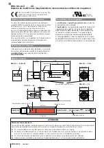
Assembling the magnetic tape
NOTICE
Damage to the magnetic tape
Hard tools may cause damage to the magnetic surface
of the tape. Even damage that appears slight (e.g.
scratches, dents) can affect linearity.
►
Do not use hard tools to install the magnetic tape!
►
Replace damaged magnetic tapes!
Magnetic tapes with an adhesive layer can be
attached using an installation aid (accessory)
(see user’s guide).
Insulator
(optional accessories, BAM TO-ML-014-01)
With increased EMC requirements, the sensor head can
be assembled in a way to insulate it completely from the
machine using two insulators. This requires two M3
threaded holes on the machine part.
►
Insert the two insulators into the 4.3 mm holes on the
sensor head to the left and right.
Assembling the sensor head
1.
Fasten the right or left side of the sensor head to the
machine part taking into account the distances and
tolerances (see page 2).
2.
Secure the screws against unintended loosening
(e.g. with locking paint).
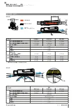
Shielding and cable routing
Defined ground!
The position measuring system and the control
cabinet must be at the same ground potential.
Shielding
To ensure electromagnetic compatibility (EMC), observe
the following:
– The cable shield must be grounded on the controller
side, i.e. connected to the protective earth conductor.
– When ducting the cable between the sensor, controller,
and power supply, it is important to avoid going near
high voltage cables due to interferences. Stray noise
from AC harmonics (e.g. from phase angle controls or
frequency converters) are especially critical and the
cable shield offers very little protection against this.
– If the sensor is supplied with voltage that is isolated
from the processing electronics, the GND for this
voltage must be connected to the GND of the proces-
sing electronics.
Bending radius
The bending radius for a fixed cable must be at least
5 times the cable diameter, with moved routing, it must be
10 times the diameter.
Cable length
Max. cable length 20 m. Longer cables may be used if
their construction, shielding and routing prevent noise
interference.
Startup
DANGER
Uncontrolled system movement
When starting up, if the position measuring system is
part of a closed loop system whose parameters have not
yet been set, the system may perform uncontrolled
movements. This could result in personal injury and
equipment damage.
►
Persons must keep away from the system's
hazardous zones.
►
Startup must be performed only by trained technical
personnel.
►
Observe the safety instructions of the equipment or
system manufacturer.
1.
Check connections for tightness and correct polarity.
Replace damaged connections or devices.
2.
Turn on the system.
3.
Check measured values in the controller and reset if
necessary.
The BML is an absolute measuring system.
When the supply voltage is switched on, the
absolute position is immediately available
without the need for a reference run. The sensor
head may not be removed from and replaced
on the magnetic tape during operation.
Setting the measuring range
Before using the measuring range must be correctly set.
Setup information can be found in the user's
guide.
Shielding and cable routing (continued)
english
www.balluff.com
4


