4-6 Optional Accessories
MN409
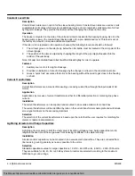
Constant Level Oiler
Description
Constant level oilers are an option for the sleeve bearing motor. Constant level oilers are used as small
supplementary oil sumps which provide an additional source of oil to replenish small amounts of oil lost
by long term leakage. They provide this feature without changing the oil level in the sump.
Operation
The device is mounted on the side of the unit and is interconnected to the bearing housing. As oil in the
bearing sump is lower, the constant level device adds oil to a pre
−
determined level. This level is set at
the factory and should not require additional adjustments.
If the oiler is to be replaced or its operation checked, the following procedure should be followed:
1.
The oil level groove on the oiler body, below the oiler bottle, must be located at the mid
−
point of the
oil level gauge.
2.
The position of the oiler is adjusted by changing the length of the pipe nipple threaded into the
bottom of the oiler body.
Note: Fill
cap on constant level oiler must be closed
tightly for oiler to operate.
Features
1.
Auxiliary source of oil for slight oil leakage.
2.
Provides an indication of rate of oil leakage by the change in oil level in the constant level oiler.
3.
Gives a ”quick look” assurance that oil is in the bearing without the need to get close to the housing
or shaft.
Current Transformers
Description
Current transformers are a means of measuring or sensing current flow through the input leads of AC
motors.
Application
Applications involve use of current transformers either for differential protection or metering line phase
current.
Installation
The current transformers can be supplied and mounted in an oversize main motor conduit box.
The current transformers will be identified by ratio on the current transformers nameplate and will include
screw type terminals on the secondary terminals.
Selection
The selection of the current transformers is based upon the ratio that the user requires for matching his
meters or related instrumentation.
Lightning Arrestors And Surge Capacitors
Description
Lightning arrestors serve to limit the crest value of incoming voltage curves. Surge capacitors tend to
lengthen the rise time of the surge wave front reducing its effects on the stator winding.
Installation
Arrestors and/or capacitors can be mounted in an oversize main conduit box. They are connected from
line leads to ground, generally as near as possible to the motor.
Selection
Standard capacitance value for surge capacitors is 1.0 mfd
−
460,575 volts, .50 mfd
−
2300
−
7000 volts.
They are suitable for 25, 40, 50, or 60 Hz systems. Arrestors are selected according to the maximum
RMS line to ground voltage.
This Manual:http://www.manuallib.com/baldor/mn409-large-ac-motors-handbook.html
Содержание Global TEFC Series
Страница 15: ...2 6 Installation Operation MN409 This Manual http www manuallib com baldor mn409 large ac motors handbook html...
Страница 35: ...A 4 API Documentation MN409 This Manual http www manuallib com baldor mn409 large ac motors handbook html...
Страница 36: ...Baldor District Offices This Manual http www manuallib com baldor mn409 large ac motors handbook html...

