background image

Flushing Procedure

NOTE:


If the system has multiple dispense

            positions, begin at the position farthest from

            the pump and move towards the pump.

1. Close fluid dispense valves at every position.

2. Once the main fluid outlet valve at the pump is closed, the air pressure to the pump 

    motor is properly adjusted and the air valve is opened.

3. Slowly open the main fluid valve.

4. Place the hose end in a waste container. Make sure hose is secure so no fluid leaks 

    during flushing.

5. Slowly open the dispense valve and allow enough fluid to pass through it to ensure that 

    the system is clean.

6. Close the valve and repeat for all dispense positions.

Apply Meter to Hose

Close the drain valve before starting this procedure.

If this installation is new or if the fluid 

in the lines is contaminated, flush the 

system before installing the meter(s).

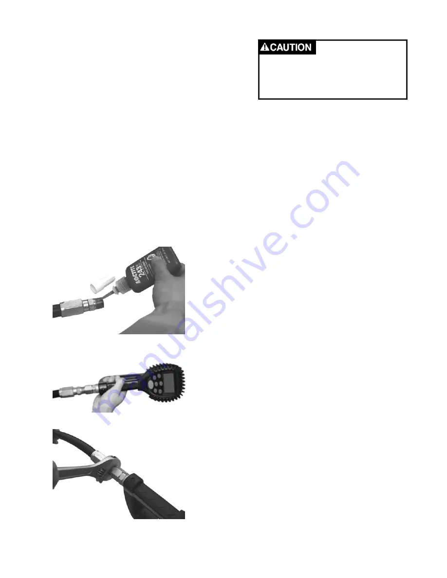
1. Attach a swivel to the meter. Apply thread sealant 

to the male end of hose. Recommended sealant is 

Loctite® 243.

2. Insert the metal end of the hose into the swivel. 

Tighten completely with an open ended, adjustable, 

wrench.

NOTE:


The threaded end of the meter always has 

female threads.  The metal end of the hose must 

have male threads.

Apply thread sealant, Loctite® 243, or equivalent, to 

the male end.

The inlet and outlet swivel connections are either 

1/2” NPT or 1/2” BSPP, depending on meter model.

Attach the hose

3

Содержание 3331-019

Страница 1: ...57 Rev D 4 12 Thoroughly read and understand this manual before installing operating or servicing this equipment OPERATION INSTALLATION MAINTENANCE AND REPAIR GUIDE RF ELECTRONIC PRESET METER Special...

Страница 2: ...pplication and use of the equipment described Should the equipment be used in a manner not specified by Balcrank Products Inc the protection provided by the equipment may be impaired Questions or Serv...

Страница 3: ...ply Meter to Hose 3 Apply Nozzle to Meter 4 METER OPERATION RF MODE 4 History Icon 5 Error Codes 6 METER OPERATION EPM MODE 7 Manual Mode 7 Batch Mode 7 Return to RF Mode 8 OPERATING MODE FUNCTIONS 9...

Страница 4: ...aged parts immediately Do NOT exceed the maximum working pressure level of the lowest rated system comp nent Use only extensions and nozzles that are designed for use with this equipment Use only flui...

Страница 5: ...r automatically shuts off when the dispense batch quantity has been reached A Top Off feature allows additional fluid to be dispensed and tracked after the batch quan tity has been dispensed Upon comp...

Страница 6: ...ound all system components according to local state and federal codes Consult the pump user s manual and other system components to ground the following 2 Pump follow manufacturer s recommendations 3...

Страница 7: ...m is clean 6 Close the valve and repeat for all dispense positions Apply Meter to Hose Close the drain valve before starting this procedure If this installation is new or if the fluid in the lines is...

Страница 8: ...battery pack is attached to the meter it automatically enters the RF Mode The trigger is in the locked out position No fluid can be dispensed by the meter until a dis pense order is received from the...

Страница 9: ...ted to the RF2 system The meter returns to the locked position The meter is now ready to receive another dispense order from the RF2 system NOTE If the original communication fails the meter automatic...

Страница 10: ...utton on the meter To retry communications with the keypad press the Reset button a second time There may be an obstruction blocking the RF2 signal between the meter and keypad It may be necessary to...

Страница 11: ...shows the amount dispensed 3 When the desired amount has been dispensed release the trigger to stop the flow 4 Press button once to reset the counter display to zero To enter the Batch Mode from the...

Страница 12: ...atch the meter is equipped with an Emergency Override See the Emergency Override section of this manual 3 The user has the option to top off the fluid at the end of a batch To top off the fluid pull t...

Страница 13: ...t set back to zero 3 Press the button while viewing Resettotal to set it back to zero 4 Release the button to return to the operating display Re settable Total NOTE The Accumulated Total cannot be res...

Страница 14: ...r is too low and meter functions are disabled Changing the Batteries The battery compartment is located in the lower case on the underside of the trigger guard 1 Turn the unit over 2 Unscrew the two s...

Страница 15: ...r comes with an option to choose 4 different Units of Measure Scale Factor Digits Unit of Measurement Programming Display 1 The actual Unit of Measure is flashing when the Programming Mode is entered...

Страница 16: ...or Save Changes When you are finished programming these options turn the unit over and press the PROGRAMMING key 1 Hold the PROGRAMMING key until the display flashes three times and goes blank 2 Press...

Страница 17: ...e buttons 5 The current unit of measure will now be flashing indicating that you have entered the programming mode Change Unit of Measure The meter comes with an option to choose 4 different Units of...

Страница 18: ...ection in the manual EPM MANUAL Mode enable disable To disable or enable the EPM mode of the meter 1 Press the button to advance to the AUTO icon on the display there will be no other icons flashing o...

Страница 19: ...tallation Use the Scale Factor showing on the display not on the trigger Changing the Scale Factor changes the accuracy of the meter potentially causing it to overfill or under fill This has the poten...

Страница 20: ...le Factor Scale Factor Viscosity in Centistokes 65o Samples of Fluids Viscosities and Scale Factors Fluid Viscosity Scale Factor 1 Water Anti Freeze 5 1 044 2 Anti Freeze 18 1 007 3 Brake Fluid 42 1 0...

Страница 21: ...1000 psi 67 bar Operating Pressure Minimum 5 psi 35 bar Operating Temperature Maximum 120o F 50o C Operating Temperature Minimum 20o F 5o C Accuracy Oils 0 5 0 5 Accuracy Anti Freeze 1 5 1 5 5 Digit...

Страница 22: ...ITEM PART DESCRIPTION 1 Battery Holder Assembly 2 Bottom Case with Screws 18...

Страница 23: ...1 2 3 ITEM PART DESCRIPTION Part Number 1 Rubber Boot 2 Display Assembly 3 RF Register Assembly Not Shown Swivel NPT Special Fluids 832935 19...

Страница 24: ...1 2 3 ITEM PART DESCRIPTION 1 Valve Assembly 2 Gear Service Kit with O ring 3 Trigger Assembly 20...

Страница 25: ...latch for batching Meter not in AUTO mode Meter not reset after prior batch Low batteries Press AUTO button and pro gram batch size Press RESET button Check for battery icon replace batteries push RE...

Страница 26: ...ETIN SB3057 Rev D 4 12 Revision Log New Release 12 07 Rev A 8 08 Added programming instructions for version 18 and Updated Warranty Statement Rev B 12 08 Added caution about tightening nozzle on page...

Отзывы: