


4.5.2.1 Displaying multiple process parameters
The procedure for displaying a single process parameter in
a text screen may be repeated to simultaneously display
multiple process parameters. To do so, proceed as follows:
1. Display the first process parameter in a text screen, as
described in the previous section.
2. Repeat Step 1 for any desired additional process
parameters, by double clicking on them in the PanaView
network tree.
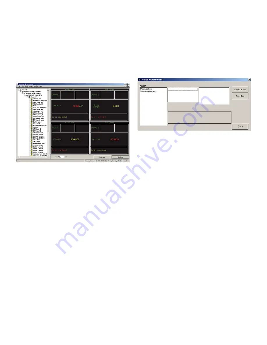
PanaView
automatically tiles the multiple
text screens in the right pane of the
Text Display
window,
as shown in
Figure 21
below.
Figure 21: Multiple text screens in the text display window
3. As in any standard
Windows®
application, the multiple
text screens may be resized by dragging their borders.
Also, the individual panes within a parameter’s text
screen may be resized by dragging the borders within
that text screen.
4. To close an open text screen, right click anywhere within
that screen, except in the title bar or the error section,
and click on the
[Remove]
option that pops up in the
context menu.
Note:
After resizing or removing any of the multiple text
screens, the default tiled layout may be restored by opening
the Window menu (see the PanaView User’s Manual) and
clicking on the Tile Output Displays option.
4.5.2.2 Displaying multiple text windows
The procedures for displaying one or more process
parameters in a single
Text Display
window may be
repeated to open multiple
Text Display
windows. To do so,
proceed as follows:
1. To open another
Text Display
window and display the
desired process parameter(s) in the new window, repeat
the steps in
“Programming the PanaView Display” on
page 40.
2. Arrange the multiple
Text Display
windows as desired
via the
Window
menu (see the
PanaView Manual
).
4.5.3 Pausing measurements
On occasion, you may wish to stop taking measurements.
With
PanaView
, you can direct the
PanaFlow Z1G/Z2G
Process Gas Flowmeter
to pause measurements without
disconnecting the power from the meter. Proceed as follows:
1. From the meter tree in the
New Meter Browser
, click on
the
PanaFlow Z1G/Z2G Process Gas Flowmeter
entry.
2. Expand the
Edit Functions
option, and double-click on
the
Pause Measurement
entry to open a window similar
to
Figure 22
below.
Figure 22: The pause measurement window
3. To pause the active measurements, double-click on the
Stop Measurement
option. The window closes and the
PanaFlow Z1G/Z2G Process Gas Flowmeter
stops taking
measurements.
4. To restart the measurements, double-click on the
Pause
Measurement
entry, and then on the
Measure Flow
option. The
PanaFlow Z1G/Z2G Process Gas Flowmeter
resumes flow measurement.
4.6 PT sensor drift and recalibration
The PT sensor is an optional accessory, that comes with
select models of Z1G/Z2G. The sensor is specified to have a
maximum drift of 0.1% of full scale (FS) output per year.
Although, the output drift of this sensor reduces over time,
as the innate stresses in the materials relax and stop
shifting around, we recommend removing the sensor for
recalibration every 5 years. However, user may decide
on the recalibration frequency based on the application
process needs, to have it calibrated earlier than the
recommended period.
When the sensor is removed for calibration, either install
the spare sensor or an approved Ex d plug to close the
sensor mounting slot. Follow all the safety precautions and
recommendations while removing and installing the sensor.
Send the sensor to the Customer Support Center addresses
mentioned on the rear cover of this manual. We will return
the calibrated sensor to the specified address, along with
the calibration certificate
27
Содержание PanaFlow Z1G
Страница 1: ...PanaFlow Z1G Z2G User s manual 910 321 Rev A...
Страница 2: ...ii...
Страница 4: ...no content intended for this page iv...
Страница 9: ...no content intended for this page 1...
Страница 21: ...Figure 12 Remote mount electronics transducer and preamplifier wiring ref dwg 702 731 732 13...
Страница 28: ...no content intended for this page 20...
Страница 30: ...no content intended for this page 22...
Страница 38: ...no content intended for this page 30...
Страница 40: ...no content intended for this page 32...
Страница 43: ...Table 13 Service record cont Date Description of service Performed by 35...
Страница 49: ...no content intended for this page 41...


