eLectRicAL
GeneRAL inFORMAtiOn
All electrical connections must be accomplished by a qualified electrician in accordance with the National
Electrical Code and in accordance with any local codes in effect at the time of installation. All electrical
connections must be made in accordance with the wiring information in this manual or on the back of
the field wiring access panel of the Equipment Module.
Connections must be made using copper conductors only. Field provided conductors, circuit breakers or fuses must be
sized to accommodate the total amperage load of the Equipment Module.
WARNING: Improper electrical connections or conductor sizing may cause the Equipment Module to
operate improperly, create the potential for an electrical hazard and may void the warranty.
CAUTION: Use only approved pressure type wire splicing or connectors suitable for the size and type of wiring used.
The electrical supply for the product must include a suitably rated switch or circuit breaker to open all ungrounded supply
conductors to comply with Section 422-20 of the National Electrical Code ANSI/NFPA 70. The disconnecting means must be
within sight and readily accessible to the user of the spa. It must be installed at least 5 feet (1.5 m) from the spa.
Connect a NO. 8 AWG (8.4mm) solid copper bonding conductor between the Equipment Module bonding lug and all other
electrical equipment and exposed metal in the vicinity as may be needed to comply with local regulations.
A PERMANENTLY CONNECTED SPA is one that is complete with pumps, heater, lighting fixtures and spa side controls.
0 vOLt inStALLAtiOn
The provided power supply cord must be connected to a receptacle with a minimum circuit
breaker size of 15 amperes. No other electrical appliance or fixture should be used on this circuit.
The heater will provide approximately 1100 watts (1.1 kw) of heat when the pump is operating in
low speed and thermostat is calling for heat.
WARNING: Under no circumstances should an extension cord be used. Use of an extension cord
will seriously degrade the performance of the equipment module and can create an electrical
hazard.
0 vOLt inStALLAtiOn
tHe FOLLOwinG inStRUctiOnS ARe FOR 0 vOLt - 0 AMpeReS AppLicAtiOnS
The following instructions must be followed for a permanently connected equipment module
designed to operate at 240 volts. The heater will provide 4500 watts (4.5kw) of heat when the
pump is on low speed and the thermostat is calling for heat.
IMPORTANT: Always refer to the product data label (Located on top of Control Box) for specific electrical
information. (Line 1, Line 2, Neutral) #8 AWG Minimum and Ground #10 AWG Minimum.
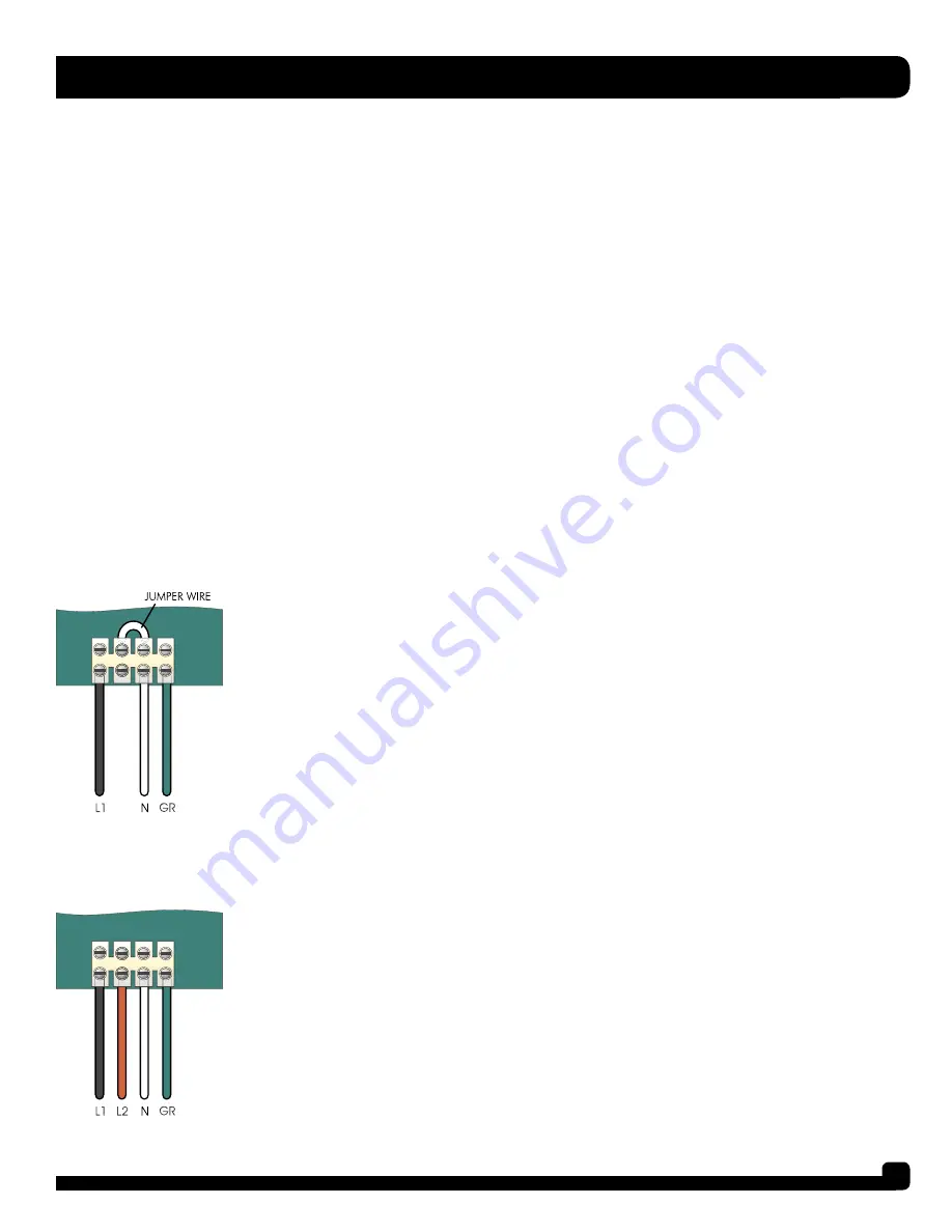
WARNING: Remove jumper wire for 240 installation (refer to 120 volt installation diagram).
1. Connect input wiring as shown. When connected to 240 volts, the equipment module requires a
3-wire electrical service, plus ground (line 1, line 2, Neutral, Ground), and requires a minimum supply
conductor ampacity of 40 Amperes.
2. Close the wiring access panel.


