background image


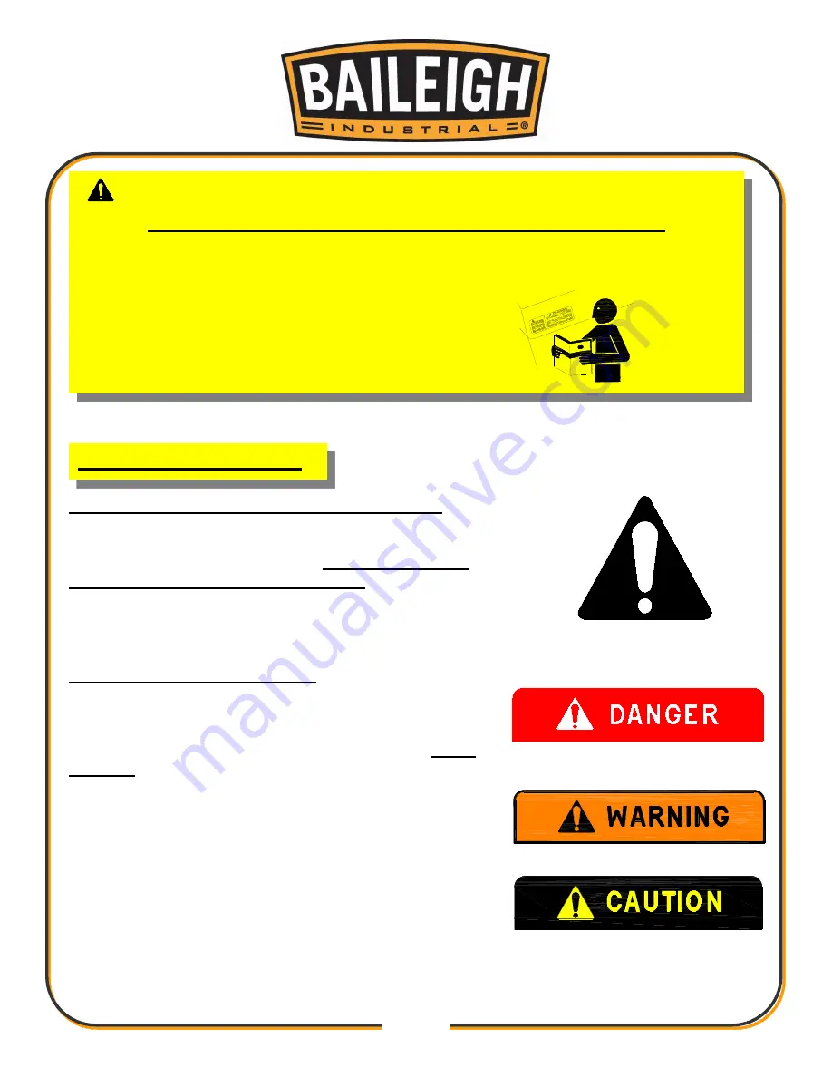
LEARN TO RECOGNIZE SAFETY INFORMATION 

 
This is the safety alert symbol. When you see this symbol 
on your machine or in this manual, 

BE ALERT TO THE 

POTENTIAL FOR PERSONAL INJURY! 

 
Follow recommended precautions and safe operating 
practices. 
 

UNDERSTAND SIGNAL WORDS 

 
A signal word 

– 

DANGER

WARNING

, or 

CAUTION 

is 

used with the safety alert symbol. 

DANGER

 identifies a 

hazard or unsafe practice that will result in severe 

Injury 

or Death


Safety signs with signal word 

DANGER

 or 

WARNING 

are 

typically near specific hazards. 
 
 
General precautions are listed on 

CAUTION

 safety signs. 

CAUTION

 also calls attention to safety messages in this 

manual. 


IMPORTANT 

PLEASE READ THIS OPERATORS MANUAL CAREFULLY 

 
It contains important safety information, instructions, and necessary operating procedures. 
The continual observance of these procedures will help increase your production and 
extend the life of the equipment. 

SAFETY INSTRUCTIONS 

Содержание SS-2822

Страница 1: ...RIAL INC IS PROHIBITED Baileigh Industrial Inc does not assume and hereby disclaims any liability for any damage or loss caused by an omission or error in this Operator s Manual resulting from acciden...

Страница 2: ...19 Setting Table Inserts 21 Attaching Cutters and Collars to Spindles 21 Assembling Fence 22 Dust Collection 23 ELECTRICAL 24 Power cord connection 25 Electrical Schematic 26 ADJUSTMENTS 27 Changing S...

Страница 3: ...ASH AND DOOR SHAPING 43 BUTT JOINTS 44 TAPER CUTS 45 TENONING 46 MAINTENANCE 47 TROUBLESHOOTING 48 BODY PARTS DIAGRAM 50 Body Parts List 51 ELEVATION PARTS DIAGRAM 52 Elevation Parts List 53 SPINDLE P...

Страница 4: ...e to Seller of any suspected defect in the Goods prior to the expiration of the warranty period The original end user must also obtain a RGA from Seller prior to returning any Goods to Seller for warr...

Страница 5: ...urther remedies provided under this Agreement or at law or equity Attorney s Fees In the event legal action is necessary to recover monies due from Buyer or to enforce any provision of this Agreement...

Страница 6: ...tion of the functional parts of the machine Capacity charts Set up and start up instructions Machine operation Scheduled maintenance Parts lists GENERAL NOTES After receiving your equipment remove the...

Страница 7: ...es a hazard or unsafe practice that will result in severe Injury or Death Safety signs with signal word DANGER or WARNING are typically near specific hazards General precautions are listed on CAUTION...

Страница 8: ...created while using machinery can cause cancer birth defects and long term respiratory damage Be aware of the dust hazards associated with all types of materials DUST PARTICLES AND IGNITION SOURCES DO...

Страница 9: ...stop button clockwise cw to reset Note Resetting the E Stop will not start the machine Dear Valued Customer All Baileigh woodworking machines should be used only for their intended use Baileigh does...

Страница 10: ...the fence Use a guard or other type of protective device at all times Use an overhead guard when the fence is removed 4 Respirator Use Always use a mask or respirator approved for wood dust when usin...

Страница 11: ...powered tools in the presence of flammable gases or liquids 19 Depth of Cut NEVER remove too much material in one pass Several light passes are safer and produce a better finish on the piece part 20...

Страница 12: ...natural wood stock It is NOT recommended to sand particle board plastics laminates medium density fiber board MDF metal glass ceramics or products containing asbestos or lead paint Some of these mate...

Страница 13: ...d for the selected RPM SAFETY LOCK NUT Never operate the shaper without the safety locking nut and spacer located on top of the spindle nut Figure 3 The lock nut has left hand threads This left hand l...

Страница 14: ...ly made by the operator INTENDED USE Purpose of the machine The machine enables semi finished products made of wood or materials based on wood to be milled with a vertical spindle The machine is desig...

Страница 15: ...be reached at 920 684 4990 and asking for the support desk for purchased machines Tech Support handles questions on machine setup schematics warranty issues and individual parts needs other than die...

Страница 16: ...rately before use As soon as you receive the spindle shaper we recommend you follow these procedures 1 Inspect packing crate for damage in transit Record damage and report it immediately to shipper 2...

Страница 17: ...e cleaner as they may damage painted surfaces Follow manufacturer s label instructions when using any type of cleaning product After cleaning wipe unpainted metal surfaces with a light coating of qual...

Страница 18: ...olts that attach the machine to the pallet Approaching the machine from the side lift the machine on the frame taking care that there are no cables or pipes in the area of the forks Move the machine t...

Страница 19: ...machine as well behind it in the places of material input and output LEVELING The machine should be sited on a level concrete floor Provisions for securing it should be in position prior to placing t...

Страница 20: ...GETING TO KNOW YOUR MACHINE A Raise Lower Handwheel B Motor Cover C Scale D Forward Reverse Switch E Power Switch F Fence Assembly G Table H Extension Table I Arbor Stabilizer Knob J Miter Gauge not...

Страница 21: ...d of the strap to the motor plate Remove using an open end wrench Fig 5 Motor Cover Installation The motor cover provides easy access to the motor and is located on the side of the shaper Once all of...

Страница 22: ...ocket head cap screws three M10 lock washers and three M10 flat washers 2 Slide the extension wing until the front of the wing is flush with the main table 3 Using a straight edge align the extension...

Страница 23: ...bottom of the quill making sure that the beveled edge of the drawbar nut B is facing upwards Fig 10 Fig 10 4 Use the spindle wrench to hold the top flats on the spindle while tightening the draw bar n...

Страница 24: ...ed in step 1 Fig 12 Attaching Cutters and Collars to Spindles Next step for spindle 1 When attaching a cutter remember to position the cutter as close to the bottom of the spindle as possible 2 Remove...

Страница 25: ...fence casting A on the table surface Fig 14 2 Use the two locking handles B provided to secure the fence casting to the table by threading the handles into the holes in the table located slightly beh...

Страница 26: ...The minimum air flow requirements for this machine are listed below The machine comes with a 4 dust port located on the side of the machine Fig 17 The dust extraction equipment is to be switched on b...

Страница 27: ...will damage the motor In the event of a malfunction or breakdown grounding provides a path of least resistance for electric current to reduce the risk of electric shock This tool is equipped with an...

Страница 28: ...ed below LENGTH AMP RATING 25ft 50ft 100ft 1 12 16 16 14 13 16 14 12 12 17 20 12 12 10 21 30 10 10 No WIRE GAUGE An undersized cord decreases line voltage causing loss of power and overheating All cor...

Страница 29: ...26 26 Electrical Schematic...

Страница 30: ...turning the handwheel B 1 To raise the spindle height turn the handwheel clockwise 2 To lower the spindle height turn the handwheel counterclockwise 3 The adjustable scale C on the front of the shape...

Страница 31: ...owever be rotated 90 from the position by using the second set of holes in the table top Fence Alignment Before using the shaper it is important to make sure that the two fence faces are parallel Use...

Страница 32: ...djustment as the belt will stretch over time The belt should yield 1 4 of deflection when squeezed together at the midpoint 1 Loosen the two hex head bolts A Fig 22 2 Slide the motor and bracket assem...

Страница 33: ...king to someone and horseplay are careless acts that can result in serious injury This section gives instructions on the basic operations of this shaper It is in no way comprehensive of every shaper o...

Страница 34: ...must be positioned further out to compensate for the material being removed Advance the outfeed side of the fence until it contacts the shaped edge of the workpiece 3 If using a miter gauge the infee...

Страница 35: ...nt results Two advantages of this setup are 2 The cut will not be affected by slight variations in the thickness of the workpiece 3 The workpiece will not be gouged if you accidentally lift it off the...

Страница 36: ...inst the grain DANGER Deep cuts require excessive horsepower and pushing force to control the cut Deep cuts can also cause the wood to splinter or split and may lead to lost control or personal injury...

Страница 37: ...t At the same time check the desired depth of cut with the blade in the 90 degree position as shown in figure 12 Depth of Cut The depth of cut is the distance from the outside circumference edge of th...

Страница 38: ...o the table to substitute for the hold ins 2 Check the rotation of the cutter Be sure to feed workpiece against rotation of the cutter 3 Feed the workpiece slowly and steadily with firm even pressure...

Страница 39: ...reate chipping out end splinters on some woods it is good practice to first shape the cross grain sides Any chipping that does occur is taken care of by the with grain cuts as shown in Figure 16 ON ED...

Страница 40: ...LAR BEARING To shape contoured edges the operator must first remove the fence assembly In order to control the workpiece and limit the depth of cut the operator must use an anti friction collar with t...

Страница 41: ...gure 22 Continue to feed the work so that the point of contact on the edge is always 90 degrees to the collar or directly in line with the cutter edge and geld firmly against it When the workpiece is...

Страница 42: ...fully position the jig for desired depth of cut and securely clamp to the table It is important with the arc and circle shapes that the workpiece prior to being shaped must be roughly cut to the desir...

Страница 43: ...se a pattern 1 Position workpiece on the table BEFORE starting the motor The operator must do the entire shaping cut by PUSHING feeding the workpiece into the cutter s 2 With a firm grip ease the edge...

Страница 44: ...d shaping the template can be constructed from several sections pieced together as shown in Figure 29 SECURING THE TEMPLATE There are various methods used to secure the template to the workpiece The e...

Страница 45: ...mplate together by hand Anchor points such as dowels are required with this type setup SPECIAL CUTS The illustrations in this section shown the profile or section views made by the cutter s The most e...

Страница 46: ...the sash cut for the first operation Figure 34 shows the stock flipped over and the sash cutter used with a 1 4 groove cutter to complete the cut Figure 35 shows the first shaping cut with the sash cu...

Страница 47: ...ge cuts which do not reduce the stock width during the cutting procedure When shaping the two workpieces one is fed top side up the other is fed bottom side up Tongued Joint Similar to the glue joint...

Страница 48: ...e outfeed fence just past the cutterhead 2 As the cut is started transfer pressure to hold the workpiece against the outfeed fence and continue feeding the workpiece through 3 After the first cut the...

Страница 49: ...ed tenons at the ends of legs for tables chairs etc Secure the leg to jig and position for cut as shown in Figure 44 Make all first cuts with the same jig setting and spindle height When the first ser...

Страница 50: ...eed tables Note Proper maintenance can increase the life expectancy of your machine Cleaning Cleaning the shaper is relatively easy Vacuum excess wood chips and sawdust and wipe off the remaining dust...

Страница 51: ...or replace cutter Cuts are unsatisfactory 1 Dull cutter 2 Cutterhead rotating in wrong direction 3 Feeding work in wrong direction 4 Gum or pitch on cutter 5 Gum or pitch on table causing erratic feed...

Страница 52: ...1 Feeding in wrong direction 1 Always feed work against the rotation of the cutterhead Depth of cut not uniform 1 Fence misalignment 2 Side pressure not uniform 1 Align outfeed fence 2 Use hold downs...

Страница 53: ...50 50 BODY PARTS DIAGRAM...

Страница 54: ...table 1 135 Lock washer 6 6 111 Extension table 1 136 Cover 1 112 Bid washer 10 7 137 Cabinet stand 1 113 Lock washer 10 7 138 Side cover 1 114 Cap screw M10x30 4 139 Nut 16 3 115 Pan HD screw M5x12...

Страница 55: ...52 52 ELEVATION PARTS DIAGRAM...

Страница 56: ...ft bolt 1 211 Gear 1 234 Key 1 212 Cap screw M8X25 9 235 Bolt bracket 1 213 Cap screw M12X50 4 236 Big washer 8 1 214 Lock washer 12 4 237 Hex bolt M8x16 1 215 Flat washer 12 4 238 Cap screw M6x12 4 2...

Страница 57: ...54 54 SPINDLE PARTS DIAGRAM Spindle and arbor is separate...

Страница 58: ...2 307 Bearing 6206 2RS 1 321 Gland 1 308 Housing 1 322 Cap Screw M10 x 30 1 309 Set Screw M6 x 8 2 323 3 4 Spindle 1 310 Lock Ring 1 324 3 4 Spindle Washer 1 2 311 Bearing 6208 2RS 1 3 4 Spindle Wash...

Страница 59: ...n 1 403 Set screw m4 7 6 4 413 Cap screw m4 7 14 2 404 Cap screw m4 7 14 2 414 Pointer miter gauge 1 405 Miter ring 1 415 Flat washer 4mm 1 406 Flat HD screw m5 8 8 1 416 Lock washer 4mm 1 407 Miter b...

Страница 60: ...57 57 FENCE PARTS DIAGRAM...

Страница 61: ...Pan screw m5x10 2 733 Nut m5 2 710 Flat washer 2 734 Elastic washer 4 711 Bar 1 1 735 Flat washer 4 712 Bar 2 1 736 1 Star knob m10 115 2 713 Guide 1 736 2 Set screw m5 8 2 714 Cap screw 2 736 3 Knob...

Страница 62: ...59 59 ELECTRICAL PARTS DIAGRAM...

Страница 63: ...2 E30 E09 Bracket 1 E31 E10 Cap screw M10X65 1 E32 E11 Cap screw M8X20 1 E33 Belt 7M690 1 E12 Flat washer 8mm 1 E34 Set screw M6X10 2 E13 Bracket 1 E35 Motor pulley 1 E14 Pan HD screw M5X12 12 E36 Hex...

Страница 64: ...AL LTD UNIT 1 FULLWOOD CLOSE SWIFT VALLEY INDUSTRIAL ESTATE RUGBY WEST MIDLANDS CV21 1QH UNITED KINGDOM PHONE 44 0 24 7661 9267 FAX 44 0 24 7661 9276 WWW BAILEIGH CO UK BAILEIGH INDUSTRIAL GMBH HOFENE...

Отзывы: