27
27
Jointer Fence Adjustment
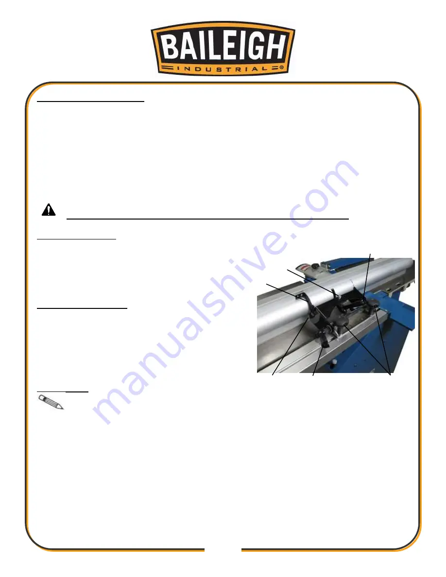
The jointer fence can adjust in three directions.
The fence can be positioned laterally along the length of the table. Typical applications will
have the fence positioned evenly over the infeed and outfeed tables.
The fence can be positioned over the width of the table. This allows for wider material up to
the full width of the cutter head. This also allows for narrower material to be cut at different
positions on the cutter head for even knife wear.
The fence can be tilted to create bevel and chamfer cuts.
For ALL fence adjustment, disconnect and lockout power to the machine.
Lateral Adjustment
Loosen the two hand knobs (A) and slide the fence
1.
left or right along the length of the table to the
desired position.
Tighten the hand knobs.
2.
Tilt Angle Adjustment
Loosen the tilt lock lever (B) and the pivot lock
1.
lever (C).
Tilt the fence to the desired angle as indicated on
2.
the scale from 90° to 45°.
Hold in position and tighten both lock levers.
3.
Stop Setting
Note
: Loosen the lock levers (B and C) just enough to allow the fence to tilt and
pivot. If the fence is too loose it will move and flex which will result in a false reading.
Slightly loosen the lock levers (B and C).
1.
Set the fence to the 90° position and place a square on the table and against the fence.
2.
If the fence is square, check if the fence is contacting the stop bolt (D).
If the fence is not square, adjust the stop bolt (D) to allow the fence to move to a square
position.
Set the fence to the 45° position and repeat the steps adjusting the stop bolt (E).
3.
Adjust the scale indicator (F) as needed to indicate the 90° and 45° positions as nearly as
4.
possible.
C
B
A
E
D
F
Содержание JP-1250
Страница 18: ...15 15 GETTING TO KNOW YOUR MACHINE T S Q N K J I H G E D C R P O M B A U L F D X B AB Z V P W AA Y H G K ...
Страница 24: ...21 21 ELECTRICAL DIAGRAM Connection Diagram ...
Страница 49: ...46 46 CABINET PARTS DIAGRAM ...
Страница 51: ...48 48 JOINTER TABLE PARTS DIAGRAM ...
Страница 53: ...50 50 CUTTER HEAD AND FEED ROLLER PARTS DIAGRAM ...
Страница 55: ...52 52 FEED ROLLER DRIVE PARTS DIAGRAM ...
Страница 57: ...54 54 PLANER TABLE PARTS DIAGRAM ...
Страница 61: ...58 58 FENCE PARTS DIAGRAM ...
Страница 63: ...60 60 NOTES ...


