background image


INTRODUCTION 


The  quality  and  reliability  of  the  components  assembled  on  a  Baileigh  Industrial  Holdings  LLC 
machine  guarantee  near  perfect  functioning,  free  from  problems,  even  under  the  most 
demanding  working  conditions.  However,  if  a  situation  arises,  refer  to  the  manual  first.  If  a 
solution cannot be found,  contact  the distributor where you purchased our product. Make sure 
you  have  the  serial  number  and  production  year  of  the  machine  (stamped  on  the  nameplate). 
For replacement parts refer to the assembly numbers on the parts list drawings. 


Our technical staff will do their best to help you get your machine back in working order. 


In this manual you will find:  (when applicable) 

  Safety procedures 

  Correct installation guidelines 

  Description of the functional parts of the machine 

  Capacity charts 

  Setup and start-up instructions 

  Machine operation 

  Scheduled maintenance 

  Parts lists 


GENERAL NOTES 

 
After receiving your equipment remove the protective container. Do a complete visual 
inspection, and if damage is noted, 

photograph it for insurance claims

 and contact your 

carrier at once, requesting inspection. Also contact Baileigh Industrial Holdings LLC and inform 
them of the unexpected occurrence. Temporarily suspend installation. 
 
Take necessary precautions while loading / unloading or moving the machine to avoid any 
injuries. 
 
Your machine is designed and manufactured to work smoothly and efficiently. Following proper 
maintenance instructions will help ensure this. Try and use original spare parts, whenever 
possible, and most importantly; 

DO NOT

 overload the machine or make any modifications. 


Note: This symbol refers to useful information throughout the manual. 

Содержание BS-128M

Страница 1: ...INGS LLC IS PROHIBITED Baileigh Industrial Holdings LLC Inc does not assume and hereby disclaims any liability for any damage or loss caused by an omission or error in this Operator s Manual resulting...

Страница 2: ...E EACH USE 20 Whenever Saw is Running 20 Breaking in a Band Saw Blade 21 Metal Chip Indicators 21 Blade Terminology 22 Width of Blade 22 Length of Blade 22 Blade structure 23 Blade type 23 SETS 24 BLA...

Страница 3: ...SAW VISE AND BASE PARTS DIAGRAM 37 Parts List 38 ELECTRICAL SCHEMATIC 43 TROUBLESHOOTING 44...

Страница 4: ...n notice to Seller of any suspected defect in the Goods prior to the expiration of the warranty period The original end user must also obtain a RGA from Seller prior to returning any Goods to Seller f...

Страница 5: ...emedies provided under this Agreement or at law or equity Attorney s Fees In the event legal action is necessary to recover monies due from Buyer or to enforce any provision of this Agreement Buyer sh...

Страница 6: ...Description of the functional parts of the machine Capacity charts Setup and start up instructions Machine operation Scheduled maintenance Parts lists GENERAL NOTES After receiving your equipment remo...

Страница 7: ...zardous situation which if not avoided will result in death or serious injury WARNING Indicates a hazardous situation which if not avoided could result in death or serious injury CAUTION Indicates a h...

Страница 8: ...le loud noises BEWARE OF CUT AND PINCH POINTS Moving saw blade may result in loss of fingers or limb DO NOT operate with guard removed Follow lockout tagout procedures before servicing EMERGENCY STOP...

Страница 9: ...modifications or alterations to a Baileigh machine Modifications or alterations to a machine may pose a substantial risk of injury to the operator or others and may do substantial damage to the machi...

Страница 10: ...e operation 15 Observe work area conditions DO NOT use machines or power tools in damp or wet locations Do not expose to rain Keep work area well lighted DO NOT use electrically powered tools in the p...

Страница 11: ...559 x 635mm TECHNICAL SUPPORT Our technical support department can be reached at 920 684 4990 and asking for the support desk for purchased machines Tech Support handles questions on machine setup sc...

Страница 12: ...ge painted surfaces Follow manufacturer s label instructions when using any type of cleaning product After cleaning wipe unpainted metal surfaces with a light coating of quality oil or grease for prot...

Страница 13: ...er gently to the floor Level the machine so that all the supporting feet are taking the weight of the machine and no rocking is taking place INSTALLATION IMPORTANT Consider the following when looking...

Страница 14: ...es a large amount of weight over a small area Make certain that the floor is capable of supporting the weight of the machine work stock and the operator The floor should also be a level surface If the...

Страница 15: ...12 12 GETTING TO KNOW YOUR MACHINE S R Q P O N M L K J I H G F E D C B A...

Страница 16: ...perate the saw with cover opened or removed H Needle Valve Controls the saw bow descent Turn cw to slow the descent or ccw to accelerate I Motor Supplies the power to drive the saw blade J Ball Valve...

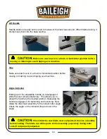
Страница 17: ...tationary This allows you to adjust the handle to the desired position Releasing the handle reengages it for tightening and loosening Now rotate the disk head assembly to the correct miter angle Check...

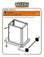
Страница 18: ...and as shown in the figure below using supplied bag of hardware WARNING For your own safety DO NOT connect the machine to the power source until the machine is completely assembled and you read and un...

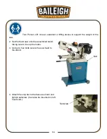
Страница 19: ...the weight of the saw 2 Set the band saw onto the assembled stand taking care to line up the holes 3 Using 4 hex bolts secure the saw head to the stand 4 Attach the stop bar to the base as shown and t...

Страница 20: ...vertical position 6 Loosen rear blade adjustment bolt and attach support bracket T 7 Unscrew and replace shoe plate U with table V 8 Attach table to bracket T with flat head bolt and nut not supplied...

Страница 21: ...indicated on the machine All line connections should make good contact Running on low voltage will damage the motor In the event of a malfunction or breakdown grounding provides a path of least resist...

Страница 22: ...ted below LENGTH AMP RATING 25ft 50ft 100ft 1 12 16 16 14 13 16 14 12 12 17 20 12 12 10 21 30 10 10 No WIRE GAUGE An undersized cord decreases line voltage causing loss of power and overheating All co...

Страница 23: ...the cut off piece can move sideways after it is cut off Otherwise it could get wedged against the blade and thrown violently Never turn the saw ON before clearing everything except the work piece ben...

Страница 24: ...s approximately 300cm of the material should be cut for breaking in If large work piece dimensions are to be cut we recommend a breaking in period of about 15 minutes After breaking in you may slowly...

Страница 25: ...easured from gullet to gullet G GAUGE The thickness of the blade H TOOTH SET The distance a tooth is bent from the blade I KERF The width of material that is removed by the blade when cutting Width of...

Страница 26: ...for transversal or inclined cutting of solid small and average cross sections or pipes in laminated mild steel and gray iron or general metal POSITIVE RAKE TOOTH 9 10 positive rake and constant pitch...

Страница 27: ...l use for materials with dimensions superior to 5 mm Used for the cutting of steel castings and hard nonferrous materials WAVY SET Set in smooth waves This set is associated with very fine teeth and i...

Страница 28: ...G A SAW BLADE A general purpose blade is furnished with this band saw To achieve a quality economical and efficient saw cut the following points must be taken into consideration Type of material being...

Страница 29: ...26 26...

Страница 30: ...ides Forcing a large width blade to cut a small radius Using a blade with an improperly finished weld joint Allowing the blade to run when not in use NEVER leave an unattended blade running MATERIAL S...

Страница 31: ...the pulley cover 5 Connect the saw into the power source Material Cutting Chart Material Speed FPM Belt Groove Used 60hz Motor Pulley Saw Pulley Tool Steel Stainless Alloy Steels Bearing Bronze 78 Sma...

Страница 32: ...ed or stainless steel section bars They require a constant drop rate to achieve a fine quality cut surface To increase the feed rate turn the needle valve control knob H counterclockwise ccw To decrea...

Страница 33: ...6 Energize the motor by pressing the green start button 7 Allow the saw to come to full speed and then begin the cut by opening the ball valve and letting the head down slowly onto the work DO NOT DR...

Страница 34: ...metal chips from the machine Inspect the saw blade for wear Check that the blade guards and emergency stop button are in good working order When through using machine lower the saw head to its rest p...

Страница 35: ...nery Co Mogul Cylinder Oil Gulf Refinery Co Medium gear oil Pure Oil Co Park Clipper Cities Service Optimus No 6 Used oil products must be disposed of in a proper manner following your local regulatio...

Страница 36: ...the blade upward with the right hand which is placed at the top of the blade 8 Remove left hand from bottom pulley and place it at the top side of the blade to continue upward pull on the blade 9 Remo...

Страница 37: ...e beginning to adjust the blade guide bearings If the blade becomes dull on one side and not the other for example it will begin cutting crooked A blade change will correct this problem the guide adju...

Страница 38: ...er from saw before adjusting This adjustment has been completed and power tested at the factory The need for adjusting should rarely occur with normal saw operation If tracking does need modification...

Страница 39: ...36 36 SAW BOW PARTS DIAGRAM...

Страница 40: ...37 37 SAW VISE AND BASE PARTS DIAGRAM...

Страница 41: ...8M 13 1 Idler Shaft Seat Block 1 14 BS128M 14 Spacer Bushing 1 15 BS128M 15 Bearing 1 16 BS128M 16 Shaft 1 17 BS128M 17 Pivot Rod 1 18 BS128M 18 Blade Must specify tooth count 1 19 BS128M 19 Distance...

Страница 42: ...Spacer 1 52 BS128M 52 Shaft Seal 1 53 BS128M 53 Spacer 1 54 BS128M 54 Key 1 55 BS128M 55 Shaft 1 56 BS128M 56 Internal Retaining Ring 1 57 BS128M 57 Blade Guide Mount 1 58 BS128M 58 Socket Head Cap Sc...

Страница 43: ...t Head Cap Screw 2 77 BS128M 77 Blade Idler Wheel 1 78 BS128M 78 Set Screw 1 79 BS128M 79 Blade Tension Adjustable Knob 1 80 BS128M 80 Blade Tension Spring 1 81 BS128M 81 Saw Blade Bow 1 82 BS128M 82...

Страница 44: ...2 Socket Head Cap Screw 2 110 3 BS128M 110 3 Block 1 110 1 BS128M 110 1 Belt Cover 1 111 BS128M 111 Socket Head Cap Screw 1 111 1 BS128M 111 1 Washer 1 111 2 BS128M 111 2 Nut 1 112 BS128M 112 Drive B...

Страница 45: ...1 Vise Body 1 302 BS128M 302 Vise Plate Movable 1 304 BS128M 304 Saw Bow Swivel Casting 1 305 BS128M 305 Acme Nut Bracket 1 306 BS128M 306 Acme Nut 1 307 BS128M 307 Acme Screw 1 334 BS128M 334 Protect...

Страница 46: ...43 43 ELECTRICAL SCHEMATIC...

Страница 47: ...eed blade an small tooth spacing Adjust to where blade does not slip on wheel Start saw and lower into work piece Adjust wheel alignment Adjust guide bearings Weld again note quality of weld Premature...

Страница 48: ...de or brush to remove chips Motor Running Too Hot Blade tension too high Drive belt tension too high Gears need lubrication Cut is binding blade Gears aligned improperly Reduce tension on blade Reduce...

Страница 49: ...Re track blade according to operating instructions Bad Cuts Rough Too much speed or feed Blade is too coarse Blade tension loose Decrease speed or feed Replace with finer blade Adjust blade tension Bl...

Страница 50: ...47 47 NOTES...

Страница 51: ...48 48 NOTES...

Страница 52: ...TOWOC WI 54220 PHONE 920 684 4990 FAX 920 684 3944 www baileigh com BAILEIGH INDUSTRIAL HOLDINGS LTD UNIT D SWIFT POINT SWIFT VALLEY INDUSTRIAL ESTATE RUGBY WEST MIDLANDS CV21 1QH UNITED KINGDOM PHONE...

Отзывы: