background image


26 

26 

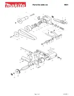
Exploded Parts List 


Item 

Part No. 

Description 

ES6100-01 

Knob 

ES6100-2 

Locating Arm 

ES6100-3 

Locating Plate 

ES6100-4 

Extension Support 

ES6100-5 

Extension Platform 

ES6100-6 

Secondary Belt Cover 

ES6100-7 

Belt Cover 

ES6100-08 

50mm Hand Knob 22x20mm Shoulder M8-
1.25 X 16 Stud 

ES6100-9 

Sanding Belt 

10 

ES6100-10 

Sanding Clamp Handle 

11 

ES6100-11 

Belt Replacing Plate 

12 

ES6100-12 

Knob 

13 

ES6100-13 

Bracket 

14 

ES6100-14 

Sanding Belt Platform 

15 

ES6100-15 

Tension Bar 

16 

ES6100-16 

Table 

17 

ES6100-17 

Spring 

18 

ES6100-18 

Roller Arm 

19 

ES6100-19 

Driver Roller 

20 

ES6100-20 

Shaft 

21 

ES6100-21 

Globular Sleeve 

22 

ES6100-22 

Micro-Inching Nut 

23 

ES6100-23 

Micro-Inching Screw 

24 

ES6100-24 

Driver Wrench 

25 

ES6100-25 

Micro-Inching Box 

26 

ES6100-26 

Knob 

27 

ES6100-27 

Tilt Scale 

28 

ES6100-28 

Washer 

29 

ES6100-29 

Motor Roller 

30 

ES6100-30 

Key 

31 

ES6100-31 

Motor 

ES6100-CAP 

Motor Starter Cap (150UF, 250V. AC) 

32 

ES6100-32 

Nut 

ES6100-32A 

Shaft 

33 

ES6100-33 

Screw 

34 

ES6100-34 

Protection Cover 

35 

ES6100-35 

Gear Case 

36 

ES6100-36 

Spring 

37 

ES6100-37 

Motor Base 

Содержание ES-6100

Страница 1: ...ITED Baileigh Industrial Holdings LLC Inc does not assume and hereby disclaims any liability for any damage or loss caused by an omission or error in this Operator s Manual resulting from accident neg...

Страница 2: ...CIFICATIONS 9 TECHNICAL SUPPORT 9 UNPACKING AND CHECKING CONTENTS 10 TRANSPORTING AND LIFTING 11 INSTALLATION 12 ASSEMBLY AND SET UP 13 Radius Table Mounting 13 End Stop Fence 14 Motor Dust Cover 14 E...

Страница 3: ...n notice to Seller of any suspected defect in the Goods prior to the expiration of the warranty period The original end user must also obtain a RGA from Seller prior to returning any Goods to Seller f...

Страница 4: ...provided under this Agreement or at law or equity Attorney s Fees In the event legal action is necessary to recover monies due from Buyer or to enforce any provision of this Agreement Buyer shall be l...

Страница 5: ...Description of the functional parts of the machine Capacity charts Setup and start up instructions Machine operation Scheduled maintenance Parts lists GENERAL NOTES After receiving your equipment remo...

Страница 6: ...zardous situation which if not avoided will result in death or serious injury WARNING Indicates a hazardous situation which if not avoided could result in death or serious injury CAUTION Indicates a h...

Страница 7: ...g machinery can cause cancer birth defects and long term respiratory damage Be aware of the dust hazards associated with all types of materials MOVING BELT ABRASIONS DO NOT place hands or fingers near...

Страница 8: ...downs safety glasses dust masks and hearing protection can reduce your potential for injury But even the best guard will not make up for poor judgment carelessness or inattention Always use common se...

Страница 9: ...othing and steel toe shoes are recommended when using machinery Wear a restrictive hair covering to contain long hair 10 Use eye protection Always wear ISO approved protective eye wear when operating...

Страница 10: ...h may impair the machines operation Repair or replace any damaged parts before operation 28 Do not remove any warning signs 29 Maintain machine in top condition Keep clean for best and safest performa...

Страница 11: ...Belt Oscillation Travel 375 9 5mm Belt Speed 3773 fpm 1150mpm Belt Blade Size 99 x 6 2515 x 152 Table Tilt degrees 0 90 Radius Roll Size Idler 2 x 6 101 6 x 152mm Overall Dimensions L x W x H 50 x 29...

Страница 12: ...age painted surfaces Follow manufacturer s label instructions when using any type of cleaning product After cleaning wipe unpainted metal surfaces with a light coating of quality oil or grease for pro...

Страница 13: ...o the floor Level the machine so that all the supporting feet are taking the weight of the machine and no rocking is taking place Follow these guidelines when lifting crane or hoist Always lift and ca...

Страница 14: ...ecuring it should be in position prior to placing the machine The accuracy of any machine depends on the precise placement of it to the mounting surface 1 Four rubber pads are furnished with the machi...

Страница 15: ...face toward the hand knob and snug into position 5 Install the table onto the support rod and secure in place with the bolt and use the nut as a jam nut to tighten the bolt into the casting Note Posit...

Страница 16: ...op fence does not drag on the belt Motor Dust Cover 1 Loosen the two hand knobs at the back of the belt housing and the hand knob for the belt cover 2 Slide the dust cover over the belt cover and unde...

Страница 17: ...indicated on the machine All line connections should make good contact Running on low voltage will damage the motor In the event of a malfunction or breakdown grounding provides a path of least resist...

Страница 18: ...ft 100ft 1 12 16 16 14 13 16 14 12 12 17 20 12 12 10 21 30 10 10 No WIRE GAUGE An undersized cord decreases line voltage causing loss of power and overheating All cords should use a ground wire and pl...

Страница 19: ...e miter gauge as needed to assist in securing the material while sanding 5 To switch off the machine push red knob Belt in vertical position and plunging table locked at lowest position CAUTION Always...

Страница 20: ...e released Allows better use of belt and helps prevent burning Sanding table and belt assembly can be adjusted from 0 horizontal 90 vertical position The belt is shown in the horizontal position Loose...

Страница 21: ...clamped by hex handle for sanding miter angles Loosen belt tension lever to remove and replace belt Return lever to tight position before starting Adjust roller to track belt while sander is running...

Страница 22: ...ertical belt position Mount fence a for flat sanding adjust to angle if needed Adjust knob to clamp bracket b for securing job Use secondary fence while using sander in the horizontal position Built i...

Страница 23: ...les The auxiliary wheel and the drive wheel are made by rubber material after the machine has been operated for long period of time the auxiliary wheel and drive wheel may be wear If this happens the...

Страница 24: ...22 22 WIRING DIAGRAM...

Страница 25: ...23 23 EXPLODED PARTS DIAGRAM...

Страница 26: ...24 24...

Страница 27: ...25 25...

Страница 28: ...100 14 Sanding Belt Platform 15 ES6100 15 Tension Bar 16 ES6100 16 Table 17 ES6100 17 Spring 18 ES6100 18 Roller Arm 19 ES6100 19 Driver Roller 20 ES6100 20 Shaft 21 ES6100 21 Globular Sleeve 22 ES610...

Страница 29: ...55 Base 56 ES6100 56 Spring 57 ES6100 57 Guide Sleeve 58 ES6100 58 Power Cord 59 ES6100 59 Width Pointer 60 ES6100 60 Connecting Plate 61 ES6100 61 Guide Pillar 62 ES6100 62 Locating Block 63 ES6100 6...

Страница 30: ...00 91 Gear Washer 92 ES6100 92 Bearing 93 ES6100 93 Socket Head Set Screw 94 ES6100 94 Bearing 95 ES6100 95 Washer 96 ES6100 96 Pan Hd Screw 97 ES6100 97 Spring Roll Pin 98 ES6100 98 Nut 99 ES6100 99...

Страница 31: ...29 29 NOTES...

Страница 32: ...30 30 BAILEIGH INDUSTRIAL HOLDINGS LLC 1625 DUFEK DRIVE MANITOWOC WI 54220 PHONE 920 684 4990 FAX 920 684 3944 www baileigh com...

Отзывы: