BA_373-E07_04_DEF_MJ_1821
21 |
36
W. Baelz & Sohn GmbH & Co.
· Koepffstrasse 5 · 74076 Heilbronn · Germany ·
www.baelz.de Seite | Page
1
+ Initialization
After Initialization
S1 in Position „S“
2
Feedback 1
U
0/2-10V
Feedback 2
I
0/4-20mA
Open-/Close-
Signal
3
Motorized Linear Actuator
baelz 373-E07
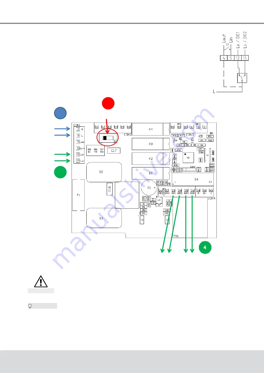
7.2.6 3-point control with a continuous output signal
1. Set the positioner up and wire to power supply as described
previously and initialize as described in section 7.5.2.
2.
Set the N↔S switch (Fig. 20, page 20
)
to "S"
3. Wire as shown in Fig. 21 (the positioner must remain connected to the
power supply throughout).
4.
The required signal can now be picked up on AO1 and AO2.
Fig. 21: Wiring diagram
3-point-signal
Fig. 22: 3-point control with a continuous
output signal - procedure
Danger of destroying the actuator!
Before any further re-initialization of the device, disconnect terminals 12 and 14
and set the N↔S switch to normal operation (N).
Caution
Tip:
An error signal showing on the red LED has no effect on the function of the
positioner. Should you wish to deactivate the error signal anyway,
set the DIP-
switch 11 to 1 ("ON") and change the following values in the menu item "CA"
using WinBas Tools (on PC, see baelz 7020 operating instructions
)
:
●
AD to 0
●
EFP to 0.0%
●
LA to 1


