Parts Identification
Accessories
(NOT TO SCALE)
11
- VENT (8x16) - A4M00771
(2)
- S
PR
IN
G
LA
TC
H
AS
SE
MB
LY
- A
4M
00
77
4
MX - BYD ID TAG (MEDIUM) WITHOUT AGES - A100240
(1)
- L
OC
KI
NG
D
OO
R
HA
ND
LE
Страница 1: ... to order replacement parts READ INSTRUCTIONS COMPLETELY BEFORE BEGINNING CONSTRUCTION INS 817220010 A BARN SHED DISASSEMBLY ENG 4 13 17 Manufacturer Backyard Discovery 3305 Airport Drive Pittsburg KS 66762 1 800 856 4445 READY SHED 8X8 BARN SHED DISASSEMBLY MODEL 817220010 ...
Страница 2: ...follow the instructions to take it apart DON T THROW ANYTHING AWAY Keep all parts during the disassembly until you are able to inventory the parts using the next Instruction Manual found in your shed crate DON T SKIP ANY STEPS This crate has been designed to keep it s parts from being damaged and from falling over Skipping steps could cause parts to fall and land on you or cause damage to your she...
Страница 3: ...2 DISASSEMBLY TOOLS REQUIRED OTHER TOOLS WE SUGGEST Utility Knife 6 Ladder Gloves Phillips Bit Driver Drill ...
Страница 4: ...ur shed or surrounding structures These instructions will take you step by step through the disassembly process Only remove screws shown in the current step do not skip foward or take out any additional screws until instructed to REMOVE ONLY THE 5 SCREWS SHOWN HERE REMOVE ONLY THIS PIECE NEXT REMOVE SCREW 2 PLS 5 8 OSB FLOOR SHEATHING W4L07734 5 8 x16 x92 1 FLOOR JOIST W4L07662 1 1 2 x3 1 2 x89 TR...
Страница 5: ...7662 1 1 2 x3 1 2 x89 TREATED 1 PARTS BEING REMOVED Only remove screws shown in the current step do not skip foward or take out any additional screws until instructed to 1 RP1 ROOF PANEL W2A02123 NEXT REMOVE SCREW 2 PLS TOP VIEW REMOVE 4 ...
Страница 6: ...move screws shown in the current step do not skip foward or take out any additional screws until instructed to PARTS BEING REMOVED TOP VIEW REMOVE SCREW 2 PLS REMOVE 1 WP5 UNIVERSAL RIGHT WALL PANEL W2A02122 5 ...
Страница 7: ...W REMOVE SCREW 2 PLS Only remove screws shown in the current step do not skip foward or take out any additional screws until instructed to PARTS BEING REMOVED REMOVE 1 WP5 UNIVERSAL RIGHT WALL PANEL W2A02122 6 ...
Страница 8: ...W REMOVE SCREW 2 PLS Only remove screws shown in the current step do not skip foward or take out any additional screws until instructed to PARTS BEING REMOVED 1 WP4 UNIVERSAL LEFT WALL PANEL W2A02121 REMOVE 7 ...
Страница 9: ...E 2 SCREWS TOP VIEW Only remove screws shown in the current step do not skip foward or take out any additional screws until instructed to 1 WP4 UNIVERSAL LEFT WALL PANEL W2A02121 PARTS BEING REMOVED REMOVE 8 ...
Страница 10: ...OVED TOP VIEW Only remove screws shown in the current step do not skip foward or take out any additional screws until instructed to REMOVE SCREW 2 PLS REMOVE REMOVE SCREW 2 PLS 1 WP3 FRONT CENTER WALL PANEL W2A02120 9 ...
Страница 11: ...TOP VIEW PARTS BEING REMOVED Only remove screws shown in the current step do not skip foward or take out any additional screws until instructed to REMOVE 1 WP2 REAR CENTER WALL PANEL W2A02119 CAUTION LOOSE PARTS BEHIND MOVE WITH CAUTION 10 ...
Страница 12: ...rent step do not skip foward or take out any additional parts until instructed to PARTS BEING REMOVED SHINGLES REMOVE SHINGLES AND LEVELING MATERIALS 11 LEVELING BLOCK W4L07756 1 1 2 x5 1 2 x6 2 LEVELING BLOCK W4L07757 1 x5 1 2 x6 2 4 CONCRETE BLOCK CB000001 1 2 CONCRETE BLOCK CB000002 2 ...
Страница 13: ...screws shown in the current step do not skip foward or take out any additional screws until instructed to PARTS BEING REMOVED REMOVE REMOVE SCREW 4 PLS REMOVE SCREW 2 PLS FLOOR JOIST W4L07662 1 1 2 x3 1 2 x89 TREATED 1 2 LP1 LOFT PANEL W2A02124 12 ...
Страница 14: ...oward or take out any additional screws until instructed to PARTS BEING REMOVED TOP VIEW REMOVE SCREW 2 PLS REMOVE NEXT REMOVE SCREW 2 PLS FLOOR JOIST W4L07662 1 1 2 x3 1 2 x89 TREATED 1 1 RP1 ROOF PANEL W2A02123 CAUTION LOOSE PARTS BEHIND MOVE WITH CAUTION 13 ...
Страница 15: ... skip foward or take out any additional screws until instructed to PARTS BEING REMOVED REMOVE REMOVE CAUTION LOOSE PARTS BEHIND MOVE WITH CAUTION DOOR DRIP BOARD W4L07675 3 4 x1 x46 3 4 20x24x1187 1 FASCIA BOARD W4L07672 5 8 x2 3 8 x87 1 4 16x60x2216 2 1 RP1 ROOF PANEL W2A02123 14 ...
Страница 16: ...3 4 VERTICAL TRIM W4L07674 5 8 x3 3 8 x44 1 2 16x86x1130 4 SUPPORT BLOCK W4L07669 1 1 2 x3 1 2 x3 1 2 6 SUPPORT BOARD W4L07668 5 8 x3 3 8 x22 1 8 16x86x562 4 7 16 OSB GABLE BRACE W4L07667 7 16 x6 1 8 x11 TREATED 6 ANGLED ROOF TRIM W4L07666 5 8 x3 3 8 x36 16x86x914 8 SIDE VERTICAL TRIM W4L07665 5 8 x2 3 8 x44 1 2 16x60x1130 4 15 ...
Страница 17: ...screws shown in the current step do not skip foward or take out any additional screws until instructed to PARTS BEING REMOVED REMOVE SCREW 3 PLS FLOOR JOIST W4L07662 1 1 2 x3 1 2 x89 TREATED 3 REMOVE SCREW 3 PLS 16 ...
Страница 18: ... VIEW CAUTION LOOSE PARTS BEHIND MOVE WITH CAUTION Only remove screws shown in the current step do not skip foward or take out any additional screws until instructed to PARTS BEING REMOVED REMOVE 1 RP1 ROOF PANEL W2A02123 17 ...
Страница 19: ...t step do not skip foward or take out any additional screws until instructed to REMOVE SCREW 2 PLS REMOVE LARGE SHEET 5 8 OSB FLOOR SHEATHING W4L07664 5 8 x43 x92 1 CAUTION REMOVING BOARD WILL REDUCE STABILTY 18 2 CONCRETE BLOCK CB000002 2 4 CONCRETE BLOCK CB000001 1 LEVELING BLOCK W4L07757 1 x5 1 2 x6 2 LEVELING BLOCK W4L07756 1 1 2 x5 1 2 x6 2 ...
Страница 20: ...ws until instructed to CAUTION REMOVING BOARD WILL REDUCE STABILTY REMOVE SCREW 2 PLS TOP VIEW 5 8 OSB FLOOR SHEATHING W4L07733 5 8 x31 7 8 x92 1 4 x 4 RUNNER W4L07670 3 3 4 x3 3 4 x92 TREATED 2 REMOVE REMOVE REMOVE REMOVE REMOVE SCREW 2 PLS REMOVE SCREW 2 PLS REMOVE SCREW 2 PLS CAUTION REMOVE PARTS WITH CAUTION 19 ...
Страница 21: ... SCREWS ON EACH SIDE AND SEPARATE A FRAME STRUCTURE Only remove screws shown in the current step do not skip foward or take out any additional screws until instructed to STOP LAY DOWN REMAINING PARTS BEFORE MOVING FOWARD REMOVE REMOVE 20 ...
Страница 22: ...M JOIST W4L07661 1 1 2 x3 1 2 x91 1 4 TREATED 2 2 WP1 SIDE WALL PANEL W2A02156 REMOVE SCREW 1 PLS REMOVE SCREW 4 PLS 21 NOW THAT THE CRATE IS FULLY DISSASEMBLED IT S TIME TO START WITH THE ASSEMBLY YOU CAN NOW FIND THE ASSEMBLY INSTRUCTION MANUAL AND GET STARTED LEAVE THESE PANELS TOGETHER ...
Страница 23: ...at you need to order replacement parts READ INSTRUCTIONS COMPLETELY BEFORE BEGINNING CONSTRUCTION INS 817220010 A 8x8 BARN SHED ENG 5 3 17 Manufacturer Backyard Discovery 3305 Airport Drive Pittsburg KS 66762 1 800 856 4445 READY SHED 8x8 BARN SHED MODEL 817220010 ...
Страница 24: ...ON To ensure proper assembly you must build your shed on a level firm surface CHECK ALL PARTS Inventory all parts listed on the Parts Identification page of this manual before beginning construction Contact our Customer Service Department if any parts are missing ADDITIONAL MATERIALS Additional materials needed and not supplied to complete your shed are listed on the Parts Identification page of t...
Страница 25: ...s with a suitable product When painting your shed there are a few key areas that can easily be overlooked that must be painted Bottom edge of all siding and trim Inside of doors and all 4 edges Smart Siding is a pre primed material see manufacturers recommended finishing MANUFACTURER S FINISHING INSTRUCTIONS DO Apply finish coat as soon as possible or within 30 days of application High quality acr...
Страница 26: ...3 OTHER TOOLS WE SUGGEST ASSEMBLY TOOLS REQUIRED Safety Glasses Gloves Pencil Tape Measure 6 Ladder 4 Level Square 1 8 Allen Wrench Drill with 3 8 Bit Phillips Head Driver Hammer ...
Страница 27: ...om any structure or obstruction such as a fence garage house overhanging branches laundry lines or electrical wires 7 10 O A 8 2 1 8 O A 5 11 5 8 DOOR OPENING 41 DOOR OPENING 22 5 67 5 7 10 1 4 7 11 5 8 O A 7 8 4x4 RUNNER 7 7 1 4 FLOOR FRAMING 1 2 1 2 7 8 FLOOR FRAMING 4 7 10 1 4 ...
Страница 28: ...LOOR JOIST W4L07662 1 1 2 x3 1 2 x89 TREATED 7 5 8 OSB FLOOR SHEATHING W4L07733 5 8 x31 7 8 x92 1 5 8 OSB FLOOR SHEATHING W4L07664 5 8 x43 x92 1 SIDE VERTICAL TRIM W4L07665 5 8 x2 3 8 x44 1 2 16x60x1130 4 ANGLED ROOF TRIM W4L07666 5 8 x3 3 8 x36 16x86x914 8 5 8 OSB FLOOR SHEATHING W4L07734 5 8 x16 x92 1 ...
Страница 29: ...8 x3 3 8 x22 1 8 16x86x562 4 SUPPORT BLOCK W4L07669 1 1 2 x3 1 2 x3 1 2 6 4 x 4 RUNNER W4L07670 3 3 4 x3 3 4 x92 TREATED 2 DOOR DRIP BOARD W4L07675 3 4 x1 x46 3 4 20x24x1187 1 FASCIA BOARD W4L07672 5 8 x2 3 8 x87 1 4 16x60x2216 2 VERTICAL TRIM W4L07674 5 8 x3 3 8 x44 1 2 16x86x1130 4 FILLER BOARD W4L07701 1 x3 3 8 x21 3 8 24x86x543 4 ...
Страница 30: ...Parts Identification Wall Panels 7 1 WP2 REAR CENTER WALL PANEL W2A02119 2 WP1 SIDE WALL PANEL W2A02156 ...
Страница 31: ...ts Identification Wall Panels 8 1 WP3 FRONT CENTER WALL PANEL W2A02120 2 WP4 UNIVERSAL LEFT WALL PANEL W2A02121 2 WP5 UNIVERSAL RIGHT WALL PANEL W2A02122 4 RP1 ROOF PANEL W2A02123 2 LP1 LOFT PANEL W2A02124 ...
Страница 32: ...L07757 1 x5 1 2 x6 2 LEVELING BLOCK W4L07756 1 1 2 x5 1 2 x6 2 LEVELING MATERIALS FULL STARTER SHINGLE 7 125 x 36 4 FULL ASPHALT SHINGLE 12 x 36 42 1 1 ASPHALT SHINGLE 12 x 30 12 3 3 ASPHALT SHINGLE 12 x 28 25 12 2 2 ASPHALT SHINGLE 12 x 22 25 14 STARTER SHINGLE 7 125 x 22 25 2 RIDGE CAP 12 17 RIDGE CAP 9 25 1 SHINGLE CAP 5 x 11 75 1 LEVELING SHINGLE 12 x 7 5 A6P0027 L 12 x 7 5 4 ...
Страница 33: ... 4 H100017 11 AC WASHER LOCK EXT 8x19 H100030 28 BG T NUT 5 16 H100074 28 BN SCREW PFH 8x1 H100085 17 BP SCREW PFH 8x1 1 2 H100086 102 BQ SCREW PFH 8x1 1 4 H100087 26 BS SCREW PFH 8x1 3 4 H100089 44 BV SCREW PFH 8x2 1 4 H100091 13 CY SCREW PWH 8x5 8 H100128 17 V BOLT WH 5 16x5 H100022 7 8x1 PFH SCREW BLK WC H100445 2 SCREW T 25 9x3 H100578 68 SCREW T 25 9x2 H100579 107 VT SCREW PFH 8x1 1 2 BLK H10...
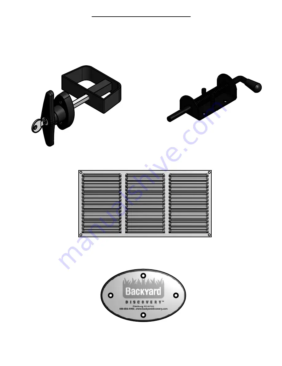
Страница 34: ...Parts Identification Accessories NOT TO SCALE 11 VENT 8x16 A4M00771 2 SPRING LATCH ASSEMBLY A4M00774 2 MX BYD ID TAG MEDIUM WITHOUT AGES A100240 1 LOCKING DOOR HANDLE 1 ...
Страница 35: ...8 19 20 21 22 23 22 21 20 19 18 17 16 15 14 13 12 11 10 9 8 7 6 5 4 3 2 1 FLUSH FLUSH Use a level to level structure Note pilot holes SCREW T 25 9x3 4 PLCS TOP VIEW IMPORTANT On a level surface make sure the floor frame is square before moving on to next step It is critical that the 4x4 Runners be touching solid ground everywhere during this step Being level is not yet a priority as we will level ...
Страница 36: ... x16 x92 1 Note Make sheathing flush to front leaving any gaps to be at the back of the shed 43 1 8 31 3 4 16 START AT THE FRONT OF THE SHED AND WORK TOWARDS THE REAR 16 00 16 00 10 10 ALL SCREWS LAND IN JOISTS BELOW PLACE SHEATHING SMOOTH SIDE UP FLUSH 10 10 Place screws at 10 apart on the front and back of all sheets Place screws at 16 apart on the center and sides of all sheets as shown always ...
Страница 37: ...ked back to the high corner Once the floor frame is level use spacers to space the center of 4x4 Runners to support the middle of your shed Leave high corner on the ground Note If needed use a claw hammer to remove dirt under the 4x4 s and blocks to make them sit level 1st 2nd 3rd Finish Start by locating the most level ground in your preferred shed locations This area must be a stable solid and d...
Страница 38: ...DOOR WP6 WP1 NOTE SIDING JOINT NOTE MAKE SURE SCREWS EITHER GO INTO RIM JOISTS OR FLOOR JOISTS WHEN MOUNTING WALLS 1 WP1 SIDE WALL PANEL W2A02156 IMPORTANT Make sure to mate the wall panel siding with joists DO NOT LEAVE ANY GAP BETWEEN THE PANEL SIDING AND ANY OF THE FLOOR JOIST ...
Страница 39: ...e fasteners approximately 3 1 2 from both the top and bottom plates WP5 FLUSH 1 WP5 UNIVERSAL RIGHT WALL PANEL W2A02122 SCREW T 25 9x3 H100578 4 16 DOOR WP1 IMPORTANT Make sure to mate the wall panel siding with joists DO NOT LEAVE ANY GAP BETWEEN THE PANEL SIDING AND ANY OF THE FLOOR JOIST SCREW T 25 9x3 4 PLCS ...
Страница 40: ... LOCK EXT 8x19 H100030 4 Q BOLT WH 5 16x3 1 4 H100017 1 V BOLT WH 5 16x5 H100022 3 IMPORTANT Make sure to mate the wall panel siding with joists DO NOT LEAVE ANY GAP BETWEEN THE PANEL SIDING AND ANY OF THE FLOOR JOIST T NUT 5 16 4 PLCS BOLT WH 5 16x3 1 4 1 PLCS WASHER LOCK EXT 8x19 4 PLCS BOLT WH 5 16x5 3 PLCS ...
Страница 41: ... BOLT WH 5 16x5 3 PLCS WASHER LOCK EXT 8x19 4 PLCS BOLT WH 5 16x3 1 4 1 PLC 1 WP4 UNIVERSAL LEFT WALL PANEL W2A02121 Q BOLT WH 5 16x3 1 4 H100017 1 V BOLT WH 5 16x5 H100022 3 IMPORTANT Make sure to mate the wall panel siding with joists DO NOT LEAVE ANY GAP BETWEEN THE PANEL SIDING AND ANY OF THE FLOOR JOIST SCREW T 25 9x3 H100578 1 ...
Страница 42: ...ssembly by securing with 3 torx drive fasteners as shown below WP4 WP6 WP1 IMPORTANT Make sure to mate the wall panel siding with joists DO NOT LEAVE ANY GAP BETWEEN THE PANEL SIDING AND ANY OF THE FLOOR JOIST NOTE MAKE SURE SCREWS EITHER GO INTO RIM JOISTS OR FLOOR JOISTS WHEN MOUNTING WALLS 1 WP1 SIDE WALL PANEL W2A02156 ...
Страница 43: ...RSAL RIGHT WALL PANEL W2A02122 20 SCREW T 25 9x3 3 PLCS SCREW T 25 9x3 H100578 4 WP5 IMPORTANT Make sure to mate the wall panel siding with joists DO NOT LEAVE ANY GAP BETWEEN THE PANEL SIDING AND ANY OF THE FLOOR JOIST SCREW T 25 9x3 1 PLC ...
Страница 44: ...0030 4 1 WP2 REAR CENTER WALL PANEL W2A02119 Q BOLT WH 5 16x3 1 4 H100017 4 IMPORTANT Make sure to mate the wall panel siding with joists DO NOT LEAVE ANY GAP BETWEEN THE PANEL SIDING AND ANY OF THE FLOOR JOIST NOTE AFTER REMOVING SAFETY BOARD OPEN AND CLOSE DOORS TO ENSURE PROPER FUNCTION BEFORE MOVING ON NEXT REMOVE SAFETY STRAP FROM DOOR REMOVE SCREW 3 PLCS ...
Страница 45: ...4 4 AC WASHER LOCK EXT 8x19 H100030 4 1 WP4 UNIVERSAL LEFT WALL PANEL W2A02121 WP4 SCREW T 25 9x3 1 PLC BOLT WH 5 16x3 1 4 4 PLCS WASHER LOCK EXT 8x19 4 PLCS T NUT 5 16 4 PLCS SCREW T 25 9x3 3 PLCS SCREW T 25 9x3 H100578 4 Q BOLT WH 5 16x3 1 4 H100017 4 ...
Страница 46: ... 25 9x2 6 PLCS SCREW T 25 9x2 6 PLCS SCREW T 25 9x2 4 PLCS SCREW T 25 9x2 H100579 22 SCREW PFH 8x2 BLK H100391 4 SCREW PFH 8x2 BLK 4 PLCS OPTIONAL For your convenience we recommend that the painting be done at this time See PAINT on page 2 of this manual ...
Страница 47: ...BOLT WH 5 16x1 3 4 2 PLCS WASHER LOCK EXT 8x19 2 PLCS T NUT 5 16 2 PLCS WASHER LOCK EXT 8x19 2 PLCS BOLT WH 5 16x2 1 2 2 PLCS FLUSH SCREW PFH 8x1 3 4 4 PLCS FILLER BOARD 2 PLCS FILLER BOARD W4L07701 1 x3 3 8 x21 3 8 24x86x543 2 BS SCREW PFH 8x1 3 4 H100089 4 BQ SCREW PFH 8x1 1 4 H100087 12 SCREW PFH 8x1 1 4 12 PLCS You will need to use the T 40 handwrench to secure the bolt and t nut combinations ...
Страница 48: ... BG T NUT 5 16 H100074 6 AC WASHER LOCK EXT 8x19 H100030 6 J BOLT WH 5 16x1 3 4 H100011 4 M BOLT WH 5 16x2 1 2 H100014 2 2 RP1 ROOF PANEL W2A02120 SCREW PFH 8x1 3 4 4 PLCS BS SCREW PFH 8x1 3 4 H100089 4 FILLER BOARD W4L07701 1 x3 3 8 x21 3 8 24x86x543 2 FILLER BOARD 2 PLCS SCREW PFH 8x1 1 4 12 PLCS BQ SCREW PFH 8x1 1 4 H100087 12 You will need to use the T 40 handwrench to secure the bolt and t nu...
Страница 49: ...GABLE BRACES 26 SCREW PFH 8x1 1 2 36 PLCS 7 16 OSB GABLE BRACE 6 PLCS 7 16 OSB GABLE BRACE W4L07667 7 16 x6 1 8 x11 TREATED 6 BP SCREW PFH 8x1 1 2 H100086 36 ...
Страница 50: ...ROOF TRIM W4L07666 5 8 x3 3 8 x36 16x86x914 4 FASCIA BOARD W4L07672 5 8 x2 3 8 x87 1 4 16x60x2216 2 VERTICAL TRIM W4L07674 5 8 x3 3 8 x44 1 2 16x86x1130 2 BP SCREW PFH 8x1 1 2 H100086 34 START HERE 2 1 3 4 5 6 ASSEMBLE THE SIDE TRIM BOARDS FIRST AND THEN ASSEMBLE FRONT TRIM BOARDS IN NUMERICAL ORDER CORNER TRIM PLACEMENT SIDE VERTICAL TRIM VERTICAL TRIM NOTE BOARD HOLE ORIENTATION TRIM CAN ONLY GO...
Страница 51: ...6x60x1130 2 ANGLED ROOF TRIM W4L07666 5 8 x3 3 8 x36 16x86x914 4 VERTICAL TRIM W4L07674 5 8 x3 3 8 x44 1 2 16x86x1130 2 BP SCREW PFH 8x1 1 2 H100086 24 ASSEMBLE THE SIDE TRIM BOARDS FIRST AND THEN ASSEMBLE REAR TRIM BOARDS IN NUMERICAL ORDER START HERE 2 1 3 4 6 5 FRONT TRIM SIDE VERTICAL TRIM CORNER TRIM PLACEMENT NOTE BOARD HOLE ORIENTATION TRIM CAN ONLY GO ONE WAY 7 8 ...
Страница 52: ... 8 PLCS The vent 8x16 is installed over the 4 1 2 holes in the front and rear center panels DOOR DRIP BOARD 1 4 CY SCREW PWH 8x5 8 H100128 8 BP SCREW PFH 8x1 1 2 H100086 4 DOOR DRIP BOARD W4L07675 3 4 x1 x46 3 4 20x24x1187 1 To ensure that water does not leak into the structure apply caulk in the grooves and along the top of the top door trim drip board DOOR DRIP BOARD INSTALLATION ...
Страница 53: ...e floor by tapping the top of the pin with a hammer Carefully drill a 3 8 hole into the floor allowing the pin to slide freely in and out of the drilled hole Repeat process for the top spring latch hole being drilled into door header Insert the handle into the hole from the outside with the handle in the unlocked position The escutcheon plate on the latch should be mounted so the long dimension is...
Страница 54: ...IDE RIGHT SIDE WORK LEFT TO RIGHT WHEN INSTALLING STARTER SHINGLES STARTER SHINGLES USE THESE STEPS FOR BOTH SIDES STARTER SHINGLE 7 125 x 22 25 1 FULL STARTER SHINGLE 7 125 x 36 2 7 8 ROOFING NAIL GALV H100446 11 22 25 STARTER FULL STARTER FULL STARTER START HERE LEFT SIDE RIGHT SIDE 22 25 STARTER 22 25 STARTER FULL STARTER FULL STARTER FULL STARTER FULL STARTER 7 8 ROOFING NAIL GALV 12 PLCS STAR...
Страница 55: ... Sealing Strip 6 3 4 TO NAILS Half Rain Slot NAIL ON TOP EDGE OF SEAL STRIP 1 1 NOTE NAIL PLACEMENT ONE NAIL ON EACH END OF SHINGLES AND ONE NAIL OVER EVERY RAIN SLOT USE DIMENSIONS ABOVE FOR NAIL LOCATIONS Familiarize yourself with a 3 Tab Shingle SHINGLE NAIL PATTERN NOTE SOME NAILS ARE NT SHOWN IN THE FIRST COURSE IN THIS PRESENTATION PRE CUTT SHINGLES WILL HAVE A NUMBER STAMPED ON THE SHINGLE ...
Страница 56: ...7 1 1 ASPHALT SHINGLE 12 x 30 5 3 3 ASPHALT SHINGLE 12 x 28 25 6 CONTINUE PLACING SHINGLES AS SHOWN USING THE NUMBERS ON THEM TO DETERMINE PLACEMENT 33 LEFT SIDE RIGHT SIDE FULL FULL FULL SHINGLES 1 FULL 1 FULL 2 3 1 2 3 Full Full Full Full Full Full Full Full Full Full Full Full Full Full 1 1 1 2 3 2 3 2 3 2 2 3 Full Full Full 1 2 3 Full Full Full 1 Repeat Courses 1st Course 2nd Course SIDE VIEW ...
Страница 57: ... TOWARDS THE REAR RIDGE CAP 12 17 RIDGE CAP 9 25 1 SHINGLE CAP 5 x 11 75 1 7 8 ROOFING NAIL GALV H100446 38 RIDGE CAP INSTALLATION IF NEEDED BEND EXCESS SHINGLES OVER PEAK BEFORE STARTING ON RIDGE CAPS 7 8 ROOFING NAIL GALV 2 PLCS RIDGE CAP 12 1 PLCS 5 1 2 ONE NAIL PER SIDE ABOVE WEATHER SEAL WEATHER SEAL TOP VIEW 1 ...
Страница 58: ...HE ONLY SHORT 9 1 4 RIDGE CAP IT WAS SPECIALLY DESIGNED FOR THE REAR OF YOUR SHED FRONT OF SHED TOP VIEW Install last ridge cap 5 back as shown it should be flush with the back of your shed 9 1 4 Install 5 Cap as shown It should be flush with the back of your shed and cover up the nails from the prior step WHEN FINISHED USE PROPER ROOF COATING MATERIAL AROUND NAILS TO PREVENT LEAKS SHINGLE CAP 5 x...
Страница 59: ... BOARD 4 PLCS Equally space the 4 support boards along the bottom of the 2 loft panels LP1 2 LP1 LOFT PANEL W2A02124 SUPPORT BOARD W4L07668 5 8 x3 3 8 x22 1 8 16x86x562 4 BN SCREW PFH 8x1 H100085 16 BS SCREW PFH 8x1 3 4 H100089 8 WE SUGGEST YOU LEVEL LOFT PANELS BEFORE SECURING TO ROOF RAFTERS ...
Страница 60: ...PTIONAL SHELF CONFIGURATION SUPPORT BLOCK W4L07669 1 1 2 x3 1 2 x3 1 2 6 BV SCREW PFH 8x2 1 4 H100091 12 SCREW PFH 8x2 1 4 12 PLCS SECURE SUPPORT 6 BLOCKS IN DESIRED HEIGHT LOCATIONS NO HIGHER THAN 43 37 ...
Страница 61: ...62 4 2 LP1 LOFT PANEL W2A02124 LP1 SUPPORT BOARD 2 PLCS SCREW PFH 8x1 3 4 4 PLCS ASSEMBLE 2 SHELVES BEFORE INSTALLATION SUPPORT BLOCK Assembled in previous step SCREW PFH 8x1 3 4 8 PLCS SCREW PFH 8x1 3 4 16 PLCS BS SCREW PFH 8x1 3 4 H100089 32 LEVEL SHELF PANELS BEFORE SECURING TO WALL STUDS ...
Страница 62: ...BRANDING PLATE INSTALLATION SCREW PWH 8x5 8 4 PLCS BYD ID TAG MEDIUM WITHOUT AGES CY SCREW PWH 8x5 8 H100128 4 MX BYD ID TAG MEDIUM WITHOUT AGES A100240 1 39 ...
Страница 63: ...erly Spring Latches can become misaligned due to building settling The building can be re leveled or adjustments can be made to the Spring Latches To adjust loosen all but 1 mounting screw and rotate it slightly until the latch pin is aligned with the hole then re install the screws My Door Handle Is Loose The handle on the inside of your door may come loose over time To tighten or re install the ...
Страница 64: ...xposed surfaces must be painted as soon as possible or within 30 days of purchase Regular maintenance is required to assure maximum life and performance of this product Failure by the owner to maintain the product according to the maintenance requirements may void this warranty Maintenance guidelines are provided in the Owner s Manual This Limited Warranty does not cover Labor for any inspection L...