RELEASE DATE
12-19-2019
REFERENCE
NUMBER
INS-2816-00
40429 Brickyard Drive • Madera, CA 93636 • USA
559.438.5800 • FAX 559.438.5900
www.bklighting.com • [email protected]
B-K LIGHTING
IMPORTANT SAFETY INFORMATION LISTED ON REVERSE
READ, FOLLOW, AND SAVE ALL SAFETY AND INSTALLATION INSTRUCTIONS
PROJECT:
TYPE:
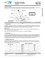
AGI2 LED
Accessory Holder
1. Remove faceplate using 1/8” Allen wrench.
2. Accessory sits in ring that rests on optic. Loosen
the thumbscrew before lifting the accessory
holder to change accessory.
3. To change or add accessory, pinch retaining
ring to remove from accessory holder. Place
accessory in holder, with honeycomb baffle
furthest from LED. Pinch retaining ring and
slide into holder, then release. Retaining ring is
tension held in place.
Smooth side of accessory lens (if used) faces
LED.
5. Install faceplate using 1/8” Allen wrench and
hand-tighten the faceplate screws in a star
pattern to 30” lbs. min.
Do not use a power tool to install screws. Do
not exceed 40” lbs.
4. Remove any dirt or debris in O-ring groove near
top of housing. Place O-Ring inside of groove.
Failure to clean groove of debris will cause
fixture to fail and void product warranty.
6. Install faceplate using 1/8” Allen wrench and
hand-tighten the faceplate screws in a star
pattern to 30” lbs. min.
Do not use a power tool to install screws. Do
not exceed 40” lbs.
5. Remove any dirt or debris in O-ring groove near
top of housing. Place O-Ring inside of groove.
Failure to clean groove of debris will cause
fixture to fail and void product warranty.
4. Place accessory holder over optic, honeycomb
baffle (If Used) furthest from LED. Retaining ring
is closest to LED. Place it back in place then tight
the thumbscrew for the accessory to be held in
place.