background image

 6

„


When selecting High-speed backup mode, for two built-in high speed backup devices 
which complete backup, SATA SUB RAID V3 will show them on LCD indicator as 

T-1

 and 

T-2

 respectively, for your convenient recording. For other more backup 

devices, SATA SUB RAID V3 will show them on LCD indicator as


T-N

, which means 

no high speed backup included. That is, SATA SUB RAID V3 will only record two 
high-speed backup devices. Furthermore, for the source device, SATA SUB RAID V3 
will show that on LCD indicator as S automatically. Following is the example 
illustrates what shows on LCD indicator when there is one source device and one high 
speed backup device.   


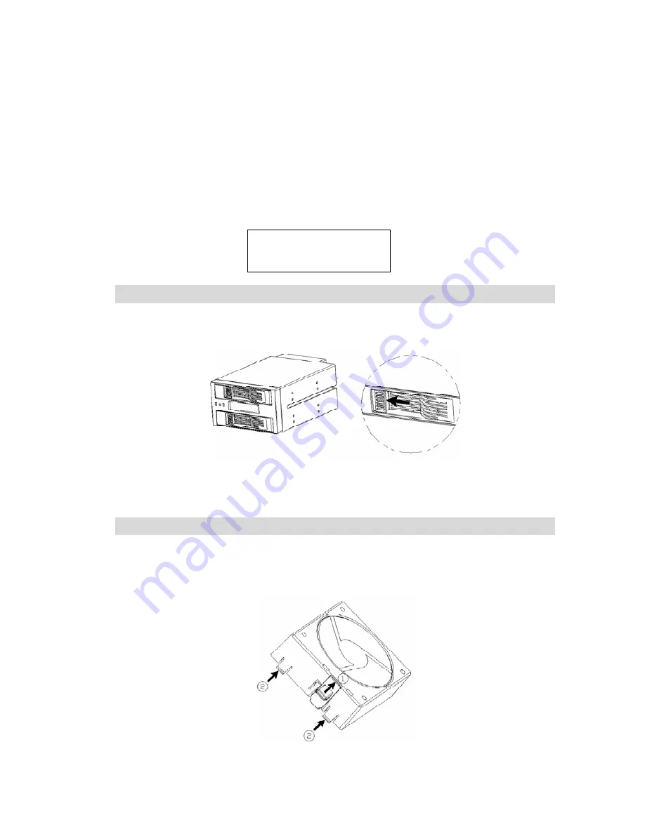
Steps of installing hard disk device 

1.


At the front of SUB RAID, slightly press down the switch of the holder in the tray, to 
the left. Then the holder will be flipped automatically.   


2.


Remove out the tray, and put Hard disk device in. Then level at the below screw hole, 
fasten and lock. (The tray supports 2.5” SATA hard disk drive.) 

3.


Push in the tray with the hard disk to the end with the holder.   

Steps of replacing the fan


1.


Remove fan stand

Push back the holder next to fan stand which is at the back of 

SUB RAID, then press two clasps fixed at the fan stand. Unlock four fixed screws and 
remove the fan.   


Pri HDD

OK

      S


Sec HDD

OK

    T1


Содержание AZ-SBC98

Страница 1: ...Installation Manual AZ SBC98 SATA SUBRAID V3 ...

Страница 2: ... is also transferring to another normal hard disk and works as usual Easy maintenance Friendly user interface allow users eliminate common errors with reducing MIS staff s loading and costs of maintaining system significantly Fault Alert The front LCD panel indicates the status of hard disk and buzzer alerts when error Plug and Play There is no need to install any software or any driver of devices...

Страница 3: ...he same brand and model Hard disks under different brands might not be workable OS Installation It s suggested that install OS in one hard disk first and copy to another one by Auto rebuild function then Data Device Installation Put in the original data device first and put in the backup device when LCD indicates OK Then the original data will be auto rebuilt and copied to the backup device Incons...

Страница 4: ...ram shows type A means Normal Backup Mode when connected and type B means High speed Backup Mode when connected Please note that the default is as Normal Backup Mode 5 Power Socket 4PIN Power Socket 6 Tray B For the tray in the secondary order 7 LCD indicator Indicating the System status and operating process 8 Buzzer switch To select alarm on or off 9 LED indicator Indicating the processing statu...

Страница 5: ...the LCD indicates as follows and it s as the complete backup at the first time Rebuilding Pri Sec Step 10 When LCD indicates following message the installation is completed Warning If the installation at the first time doesn t follow above steps and the HDD 1 HDD 2 tray are put at the same time then power on SATA SUB RAID wouldn t identify which one is source device and it would cause data loss wi...

Страница 6: ...adopting High speed backup at the first time the system will auto rebuild completely After re build is completed and remove the backup device the system will record what content changes in the future When the backup device is put into SATA SUB RAID V3 again the system will also enter High speed re build mode automatically and SATA SUB RAID V3 supports two backup devices for High speed mode Please ...

Страница 7: ...xample illustrates what shows on LCD indicator when there is one source device and one high speed backup device Steps of installing hard disk device 1 At the front of SUB RAID slightly press down the switch of the holder in the tray to the left Then the holder will be flipped automatically 2 Remove out the tray and put Hard disk device in Then level at the below screw hole fasten and lock The tray...

Страница 8: ...clasp linking to the connector on the holder and remove the connector 4 Replace the new fan in the reverse direction Service For any questions or problems please use our Email Hotline info azenx com or our Phone Hotline 1 510 498 8888 AzenX is a brand of Dynatron Corporation Tel 1 510 498 8888 Fax 1 510 498 8488 Email sales dynatron corp com Website www dynatron corp com ...

Страница 9: ...8 www azenx com ...

Отзывы: