Azbil KFDB Скачать руководство пользователя страница 41

35

7-6.  Troubleshooting

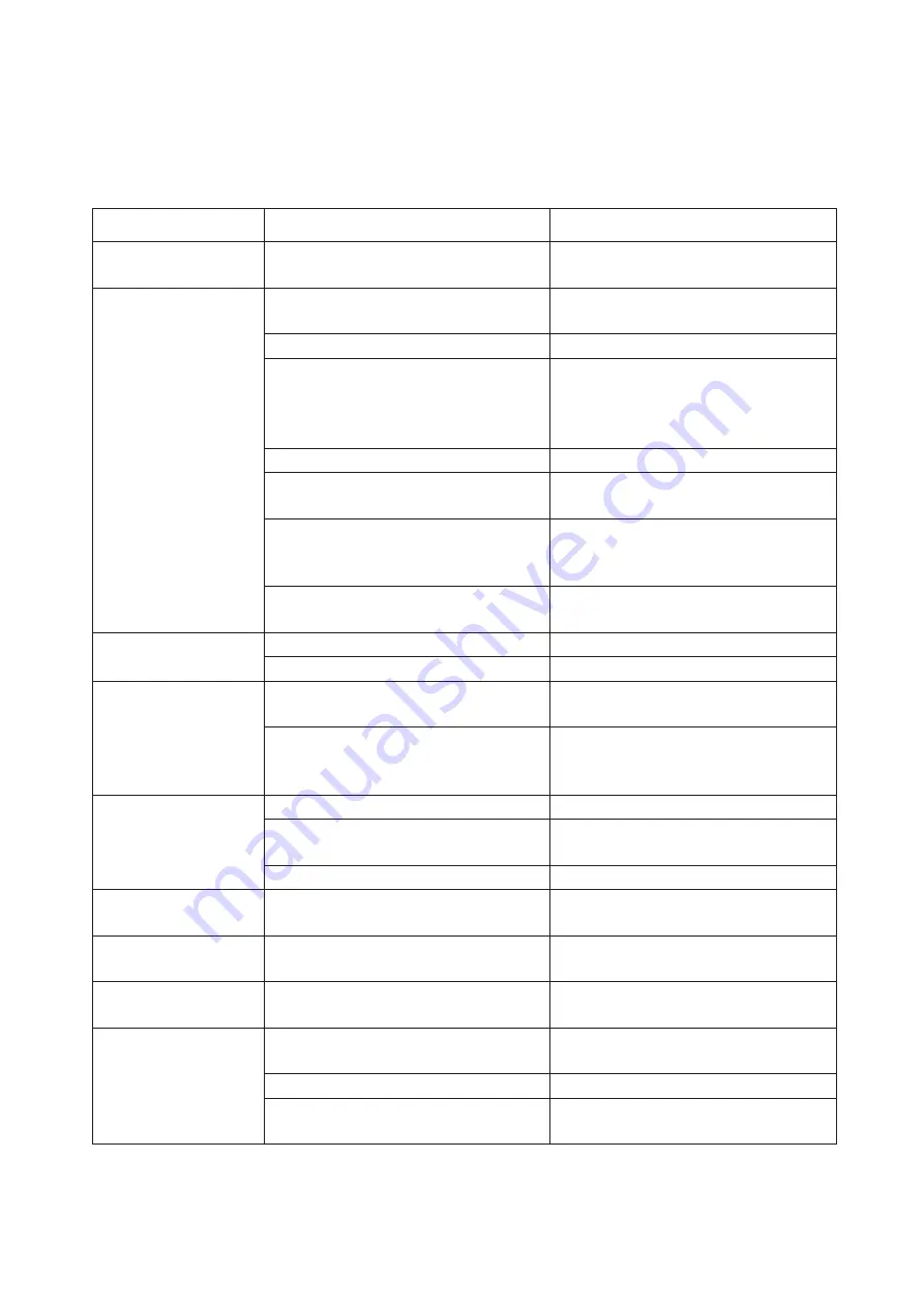
Symptoms of troubles, probable causes, and remedies are shown in the following table. For 
adjustments, refer to the preceding section.

Symptom

Probable cause

Remedy

Pilot relay whines.

Stained valve stem (section hitting the port) Take out pilot relay and clean the valve stem 

(section hitting the port)

No or only very low 
controller output pressure 
is delivered.

No air supply is provided or air supply 
pressure is lower than 140 kPa {1.4 kgf/cm

2

).

Provide an air supply of correct pressure.

Restriction is clogged.

Take out and clean the restriction.

Restriction is not correctly installed.

Parts (restriction, blind plug, etc.) differ by 
whether instrument is incorporated with 
transmitter or not. Install correct parts at 
correct positions.

Filter is stained.

Replace filter.

Air leak in nozzle circuit of controller unit. Check that O-rings are properly installed. 

Securely tighten the controller unit.

Leak or clogging of A/M transfer circuit (for 
instrument with A/M transfer provision)

Take out manual loader unit, inspect its 
circuit, check that O-rings are properly 
installed, and securely install the unit.

Leak in pilot relay diaphragm section

Take out pilot relay and inspect diaphragm. 
If leak is found, replace diaphragm.

Controller output 
pressure is too high.

Nozzle of controller unit is clogged.

Clean the nozzle.

Stained valve seat of pilot relay

Take out pilot relay and clean the valve seat.

Indication is with large 
input offset.

SP or PV pointer is shifted.

Re-adjust deviation generating mechanism 
and indicating mechanism.

Controller mechanism is not properly 
adjusted. (Balancing of proportional band is 
improper.)

Adjust balancing of controller mechanism.

Integral rate is shifted, 
or integral action is 
ineffective.

Damaged needle or seat

Replace needle assembly with new one.

Clamping screw of dial is loose.

Set the dial in the correct position and fix it 
securely with screw.

Air leak of gasket

Securely fix to base.

Manual loading pressure 
is low.

No air supply is provided or air supply 
pressure is lower than 140 kPa {1.4 kgf/cm

2

}.

Provide proper air supply.

Manual loading pressure 
is high.

Valve stem of pressure regulator valve is 
stained or dusty.

Overhaul the pressure regulator.

Zero point shifts largely 
when ranges are changed.

Transmitter section is not properly adjusted. Adjust and calibrate transmitter section.

Output is unstable or 
pulsates.

Air leak

Check and correct air connections and 
gaskets.

Stained nozzle/flapper

Clean the nozzle/flapper.

Stained pilot relay

Take out and clean the pilot relay. Replace it 
as required.

Содержание KFDB

Страница 1: ...OM2 6220 0000 Field Mounted Indicating Controller Model KFDB KFKB KFLB User s Manual...

Страница 2: ...s for a particular purpose and makes no express warranty except as may be stated in its written agreement with and for its customer In no event shall Azbil Corporation be liable to anyone for any indi...

Страница 3: ...ve 16 Chapter 4 CALIBRATION AND ADJUSTMENT OF TRANSMITTER SECTION 17 4 1 General 17 4 2 Calibration of Differential Pressure Transmitter 17 4 3 Calibration of Gauge Pressure Transmitter 19 4 4 Calibra...

Страница 4: ......

Страница 5: ...instrument can be converted to measure a flow differential pressure liquid level or pressure simply by changing the detector elements 1 2 Structure Mechanically the instrument consists of a detector...

Страница 6: ...sure Flange type Remote sealed type High working pressure type KFDB11 22 KFDB33 KFDB44 KFDB61 62 KFDB71 72 KFDB81 82 OM2 5220 1100 Pressure High pressure Low pressure Absolute pressure Remote sealed t...

Страница 7: ...3 Fig 1 2 Layout of Internal Components...

Страница 8: ...tial gap P external reset or PD external reset Proportional Band P 5 to 500 direct or reverse action Integral Time I 0 05 to 30 minutes Derivative Time D 0 05 to 30 minutes Differential Gap Adjustable...

Страница 9: ...ight JIS F 8001 Class 3 splash proof NEMA 3 IEC IP 54 Materials Case Aluminium diecast Cover Glass fiber reinforced polyester resin Finish Baked acryl paint corrosion resistant paint and silver paint...

Страница 10: ...l is converted into force by the feedback bellows and vector component F1 is fed back to the beam via the strap as shown in Fig 1 3 thereby making up a feedback loop which brings the beam into equilib...

Страница 11: ...splacement to drive the meter pointer At the same time the mechanism provides another deviation signal which is fed to the controller mechanism which renders proportional integral and or derivative ac...

Страница 12: ...lapper pin which is linked with the feedback link to change the gap between the nozzle and flapper thereby changing the nozzle back pressure The nozzle back pressure is amplified by the pilot relay to...

Страница 13: ...e restriction and capacity chamber of the integral unit in order to provide an integral I action By adding the deriva tive unit a derivative D action can be attained A derivative bellows is provided i...

Страница 14: ...d by replacing the feedback chamber of the proportional unit with a spring and feeding the output pressure of the pilot relay to the integral chamber The differential gap width is adjustable for a ran...

Страница 15: ...tic control output pressure of the controller As you press the check button the gauge indicates the pressure regulator output manual loading pressure When in the MAN mode the transfer lever set in the...

Страница 16: ...ceives an external pneumatic pressure setting signal 20 to 100 kPa 0 2 to 1 0 kgf cm2 and converts it into mechanical displacement which is fed via the overtravel link to the deviation generating mech...

Страница 17: ...e and from mechanical vibration 2 2 Air Supply The air supply must be dry and clean 2 3 Air Connection Ports The air connection ports are provided at lower sections of the controller and are of a Rc 1...

Страница 18: ...14...

Страница 19: ...the process to be controlled 3 3 Instrument With Manual Loader 3 3 1 Manual Operation First stabilize the process by manual operation Set the A M Selector lever to the M position and adjust the press...

Страница 20: ...that the pneumatic controller output signal increases and saturates Proportional band P PROP BAND dial at 50 Integral time I RESET dial at 0 05 minutes 3 Set the output pressure at the desired batch s...

Страница 21: ...of the instrument 4 2 Calibration of Differential Pressure Transmitter 1 Release the low pressure connection port marked L to atmosphere 2 Connect to the high pressure connection port marked H a varia...

Страница 22: ...comes 100 1 4 4 99 If the output is lower than 100 turn the boss so that the output becomes higher than 100 by an amount of 1 4 of the shift For example if the output is 98 turn the boss so that the o...

Страница 23: ...higher than 100 turn the boss so that the output becomes lower than 100 by an amount of 1 4 of the shift For example if the output is 104 turn the boss so that the output becomes 100 1 4 4 99 If the...

Страница 24: ...ube using a thread or fine wire looped into two circlets 4 5 1 Calibration Formula and procedure for Liquid Level Transmission 1 To calculate the weight buoyancy for calibration use the following form...

Страница 25: ...ss so that the output becomes lower than 100 by an amount of 1 4 of the shift For example if the output is 104 turn the boss so that the output becomes 100 1 4 4 99 If the output is lower than 100 tur...

Страница 26: ...b Calibration weight F corresponding to buoyancy F D2 H H L 4 1 D2 H H L where H High limit of specific gravity range 4 5 4 Adjustment of Stopper 1 When the instrument is shipped from the factory the...

Страница 27: ...23...

Страница 28: ...24...

Страница 29: ...se type of instrument 3 Inset the adjustment pin 1 2 mm dia through the adjustment pin hole 4 If the SP pointer has not been accurately aligned with the PV pointer align it accurately by means of the...

Страница 30: ...y 59 1 kPa 443 mmHg is sealed in the integral chamber of the controller Since this pressure may vary if the controller is left in this state for a prolonged period of time perform the above procedures...

Страница 31: ...kPa 300 mmHg by adjusting the PV input d Change the integral reset and derivative rate dials to the fully closed state 30 minutes or more e Balance the controller output pressure at 80 kPa 600 mmHg b...

Страница 32: ...ustment in a similar manner as in the case of 1 3 Adjust the length of the deviation link so that the deviations read in 1 and 2 become identical values but in reverse directions The length becomes sh...

Страница 33: ...es of angle Turning the pin clockwise set the pin groove horizontally at the side that the link falls 2 Set the setpoint at 50 Set the differential gap setting dial at the minimum 0 position of the IN...

Страница 34: ...oint as follows a Connect the instrument output OUT connection port a pressure gauge of Class 0 5 better b Set the proportional band setting dial of the controller mechanism to the INC MEAS DEC OUT st...

Страница 35: ...pressure 20 to 100 kPa 0 2 to 1 0 kgf cm2 to the ESP connection port of the instrument Fig 6 1 1 Zero Adjustment Apply 0 input and adjust the ZERO ADJ knob of the travel link so that the PV pointer i...

Страница 36: ...t knob If the error is in the positive side of the scale shorten the travel link turn the knob counterclockwise as viewed from the instrument bottom c The zero point also will vary as the travel link...

Страница 37: ...the stained filters Clean the dirty restrictions using a needle wire of 0 12 mm diameter 7 2 Controller Unit 1 Turn off the air supply and remove the deviation link 2 Remove the four screws of the bas...

Страница 38: ...32 Fig 7 2 Maintenance of Controller Unit...

Страница 39: ...HOUSING 1 4 GUIDE PIN 6 5 CONICAL SPRING 1 6 WASHER 1 7 SPRING 1 8 NOZZLE 1 9 WASHER 1 10 SEAL 1 11 DIAPHRAGM LOWER 1 12 EXHAUST RING OUTER 1 13 EXHAUST RING INNER 1 14 AREA PLATE 1 15 WASHER 1 16 DIA...

Страница 40: ...on 3 3 2 Apply a deviation in the direction that the AUTO output is decreased Turn the SP knob so that SP is smaller than PV when in the reverse action or SP is greater than PV when in the direct acti...

Страница 41: ...y and inspect diaphragm If leak is found replace diaphragm Controller output pressure is too high Nozzle of controller unit is clogged Clean the nozzle Stained valve seat of pilot relay Take out pilot...

Страница 42: ...36 Pneumatic Circuit Diagram...

Страница 43: ......

Страница 44: ...o your use 3 Measures to be taken to secure the required level of the reliability and safety of your Equipment in your use Although azbil is constantly making efforts to improve the quality and reliab...

Страница 45: ...argin of your machine or equipment you are required to renew any Azbil Corporation s products every 5 to 10 years unless otherwise specified in specifications or instruction manuals System products fi...

Страница 46: ......

Страница 47: ...Document Number OM2 6220 0000 Document Name Field Mounted Indicating Controller Model KFDB KFKB KFLB User s Manual Date 7th edition Jan 2020 Issued Edited by...

Страница 48: ......

Отзывы: