UMAX140900. Ethernet to CAN Converter. Version 5
Page: 22-35
6
CONVERTER DEPLOYMENT
There are two major approaches in using the Ethernet to CAN converter. One is to use the
converter on its own as a CAN extender or a baud rate converter.
For example, a pair of coupled converters can synchronize two CAN networks. This example
can be extended to several CAN networks running at different baud rate in various remote
locations, connected together using the Ethernet to CAN converters.
The second approach is to use the converter together with other IP devices that can directly
communicate with the converter over the IP network. This approach requires writing a custom
software for interfacing with the converter. Since the converter uses a proprietary
communication protocol, Axiomatic provides the CAN-ENET Software Support Package (SSP),
p/n AX140910, for interfacing with the converter. The SSP is downloadable from
, log-in section.
The majority of Axiomatic PC software tools support the Ethernet to CAN converter. They can
connect to the CAN bus using the Ethernet to CAN converter the same way as they connect to
the bus using the USB to CAN converter. The Axiomatic Electronic Assistant
®
(EA) can
communicate with the converter starting from version 5.11.82.0, and the CAN Assistant
–
Scope and CAN Assistant
– Visual support the converter starting from version 3.0.0.
The use of the Ethernet to CAN converters for synchronizing CAN networks with or without
baud rate conversion is described below. There is no need for custom software for this type of
the converter deployment.
6.1 CAN Network Synchronization
To synchronize two remote CAN networks, the user can simply connect an Ethernet to CAN
converter to each of the CAN network and configure the converters the way that they will talk
with each other.
6.1.1 Hardware Setup
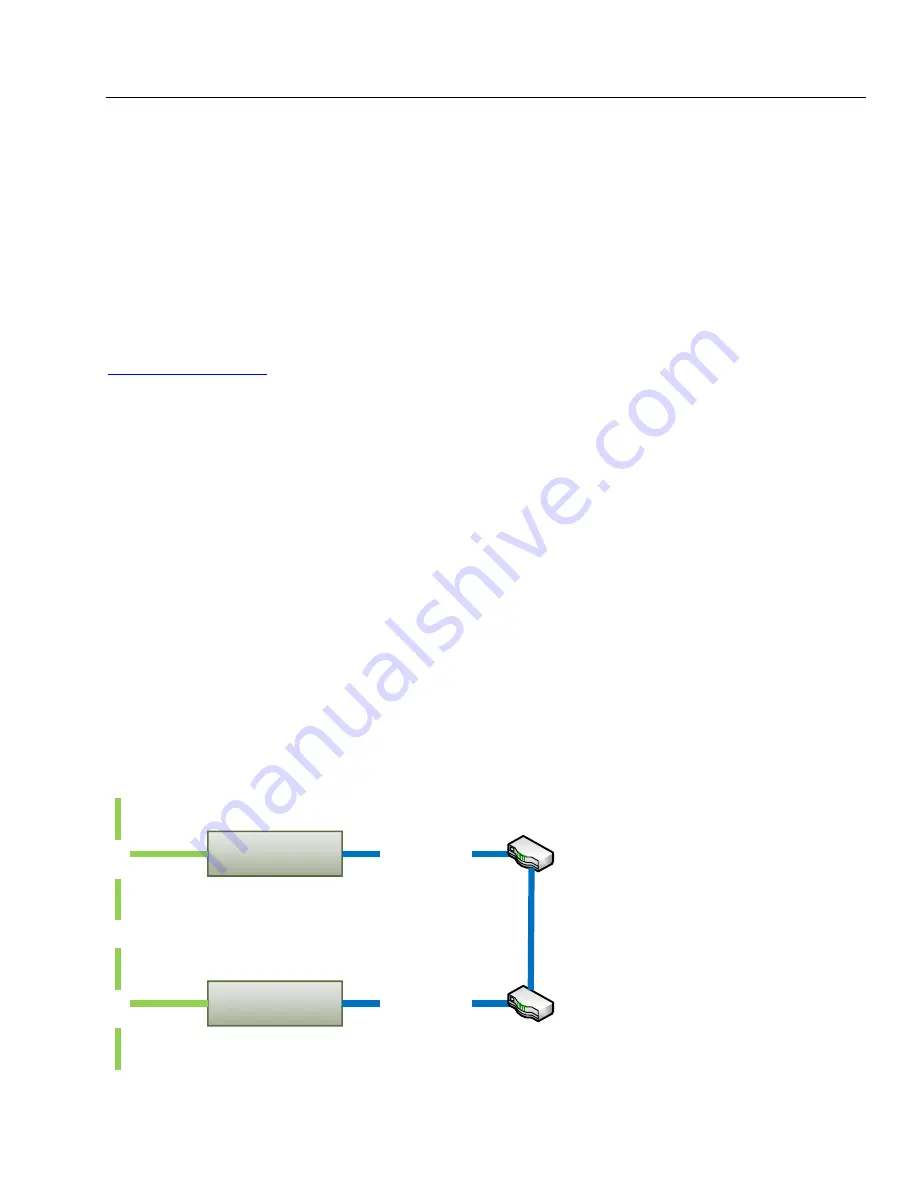
The converters should be connected together through a local or global IP network, see: Figure
20 and Figure 21.
C
A
N
1
Ethernet to CAN Converter
1
Ethernet cable
C
A
N
2
Ethernet to CAN Converter
2
Ethernet cable
LAN
Figure 20. Local Connection through the LAN


