background image

Axia

®

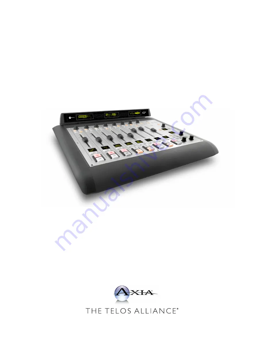
 iQx 

AES67 Console with Integrated Engine

Installation & User’s Guide

Version 1.0  November, 2018 

1490-00203-001 --- USER MANUAL: AXIA IQX

TelosAlliance.com

Содержание iQx AES67

Страница 1: ...Axia iQx AES67 Console with Integrated Engine Installation User s Guide Version 1 0 November 2018 1490 00203 001 USER MANUAL AXIA IQX TelosAlliance com...

Страница 2: ...an easily accessible safety disconnect device should be included in the rack design To reduce the risk of electrical shock do not expose this product to rain or moisture This unit is for indoor use on...

Страница 3: ...Alliance which are mentioned in this manual or accompanying material are informational only The Telos Alliance makes no endorsement of any particular product for any purpose nor claims any responsibil...

Страница 4: ...r which must be written on the exterior of your shipping container Please do not include cables or accessories un less specifically requested by the Technical Support Engineer Be sure to adequately in...

Страница 5: ...0 E Fader 10 F Mix Bus Assignment Buttons 10 G Option Knob 11 Monitor Section 12 A MeterToggle Button 12 B Clock Timer Buttons 12 C Record Button 12 D Show Profile Button 12 E Studio Knob 12 F Studio...

Страница 6: ...le GPIOTable 36 Phone Profile GPIOTable 37 Codec Profile GPIOTable 38 Operator Microphone Profile GPIOTable 39 CR Producer Microphone Profile GPIOTable 40 CR Guest Microphone Profile GPIOTable 41 Stud...

Страница 7: ...ol 54 Synchronization 54 Backup Restore 55 General System Setup 55 Code Updates 55 A Appendix Mechanical 57 B Appendix TearSheets SpecificUseCaseConfigurations 59 AES67 input 59 AES67 output 59 On Air...

Страница 8: ......

Страница 9: ...thatinspireourcustomerstocreatethemostexcitingandengagingaudioexperiencesimaginable We re grateful that you have chosen audio tools from Telos Systems Omnia Audio Axia Audio Linear Acoustic 25 Seven S...

Страница 10: ......

Страница 11: ...xpansion modules Connect the uplink port A to a 1 gigabit ethernet link on your switch Connect power B to either power ports Connect expansion modules optional to the expansion module ports C Flip the...

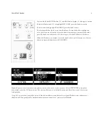
Страница 12: ...Do these steps to edit the IP address of the device When the IP address is complete rotate the knob to the top of the menu two dots are shown and press the knob to exit IP ADDRESS Repeat the procedur...

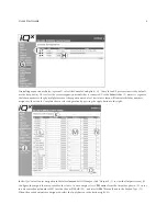
Страница 13: ...cate the fader numbers assigned to the module Complete the console configuration by pressing the Apply button to the right In the iQx Control Center navigation in the left column under IO Manager clic...

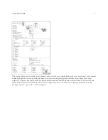
Страница 14: ...een S Enter the word TONE into the Source name field T Select the Sine 1kHz Tone 20dBFS from the Source Input U Complete the profile generation by pressing the OK button V The screen will return to th...

Страница 15: ...tating the knob select the source by pressing the knob Make sure you have the channel assigned to Program 1 by pressing the PGM1 button at the top and also that the monitor section also has PGM1 selec...

Страница 16: ......

Страница 17: ...oosing Axia as your choice in AoIP studios We know there are many options available to you and believe you will be satisfied with your purchase thanks to the ease of setup technical support and reliab...

Страница 18: ...two 8 fader sidecars and or adding user friendly Telco control or User buttons The main module and all three sidecars are designed for tabletop placement no cutouts in the table are needed other than...

Страница 19: ...ed to change its source profile but is prevented from doing so because the channel is in the ON state Turn off the channel to clear the issue 2 OFF button illuminated while ON blinks in 1 second inter...

Страница 20: ...be adjusted by the Fader Offset setting under Customize Fader Options in the web UI The fader position may also impact the ON OFF state of the channel if the profile is defined with a Fader Start or F...

Страница 21: ...ode branch is only available to source types that support stereo The Backfeed branch is only available to sources that produce mix minus The source profile can define some of the menu items to be filt...

Страница 22: ...essed again to stop the timer The RESET button will set the timer back to zero C Record Button The RECORD button will trigger the record mode as it is defined in the Show Profile Refer to Show Profile...

Страница 23: ...ons are labeled EXT n external and are assigned to any source A typical use case is to monitor the tuner set to your frequency and thus monitor what is broadcast on the air via the ON AIR Monitor The...

Страница 24: ...figure the two displays for audio meters to be in one of three count modes 2 meters 3 meters or 4 meters In 2 Meters Display the audio meters will span the full width of the displays The METER button...

Страница 25: ...icates a single phone line to channel source profile If the optional iQx 6 Fader with Telco sidecar is added to the system the operator could make and receive phone calls If no Telco sidecar is added...

Страница 26: ...econd phone interface The 6 displays present the state of the 6 possible phone lines There are two DROP buttons F for dropping calls one for each column phone interface Any phone line not in a LOCKED...

Страница 27: ...tion at a GPIO port in channel logic or within Axia Pathfinder Routing Control The button will illuminate when the other end triggers the appropriate command The two sets of five buttons make up a tot...

Страница 28: ......

Страница 29: ...files Show Profiles and Audio Output It should be noted that you access the main configuration of the iQx with a browser application same used to surf the internet and typing the IP of the iQx in the...

Страница 30: ...It also mutes CR monitors and Preview when ON CR Guest Microphone Used for any other guest mic in the control room Its associated logic automatically mutes the CR monitors and Preview when ON Studio...

Страница 31: ...advertised sources Livewire a Livewire channel number 1 32767 is expected The Browse button will show any sources discovered through the Livewire discovery channel Livewire Backfeed a Livewire channe...

Страница 32: ...sired in some applications thus this option Input Trim Gain This setting allows you to specify an amount of gain from 25 to 25 dB Fader Trim Gain is applied in the signal path just before the fader Pa...

Страница 33: ...le if your source is a Control Room mic and you only want it to appear on the left most fader you would check only the box marked Channel 1 For sources only for monitoring uncheck all Channels to prev...

Страница 34: ...lt uses only the software button soft button next to the Preview button to control the state of the interface on hook off hook Channel ON Answers Hybrid GPIO control of a phone interface would be trig...

Страница 35: ...ay be chosen by the operator on the fly by depressing the Options control When the control is pressed the display will list the options that you ve checked as Enabled in this section of the configurat...

Страница 36: ...In the center B the row is divided into two rows The top row is for enabling the option at show profile load while the bottom is for locking the state so the operator is not able to make changes to t...

Страница 37: ...nitor Section The monitor section is divided into four columns for each of the monitoring points CR Monitor the control room is where the surface resides CR Headphone the operator of the surface Previ...

Страница 38: ...nage if sources are to be used for mix channels monitor or both External 1 and 2 the monitor section has two EXT buttons as preset buttons to route an external source to the monitors Defining a profil...

Страница 39: ...mer on the overbridge is triggered manually or by those source profiles with timer control enabled Preview Interlock Mode allows for the function of pressing a second Preview button that would release...

Страница 40: ...ogram 4 are the four standard output mixes Record is a special mix driven by the P4 button phone handset icon and is a mix which is Pre ON and Post Fader Phone is another special mix driven by the P4...

Страница 41: ...ast is that the receiving end issues a SIP request from the transmitter device The Channel IP field is used to define the multicast value If unicast is declared this field will populate with a SIP URI...

Страница 42: ......

Страница 43: ...channel ON or channel Preview state Codec links to remotes may require IFB communication and GPIO may be a means to trigger the appropriate states Operator Microphone the operator of the console has a...

Страница 44: ...ll support The Axia GPIO ports are 15 pin Some of the pins are not reflected in the tables because the pins of power are common pins as shown below Pin 7 GPO common pin Typically tied to GND by applic...

Страница 45: ...RESET Command Pin 14 Momentary turns OFF the channel w o generating a GPO STOP pulse GPI 5 READY Command Pin 15 Latch to indicate READY OFF button illuminated for profiles defined with the READY enabl...

Страница 46: ...e PREVIEW OFF GPI 4 Not used Pin 14 GPI 5 READY Command Pin 15 Latch to indicate READY OFF button illuminated for profiles defined with the READY enable Outputs GPO ID Name Pin Notes GPO 1 NEXT pulse...

Страница 47: ...REVIEW OFF GPI 4 Not used Pin 14 GPI 5 READY Command Pin 15 Latch to indicate READY OFF button illuminated for profiles defined with the READY enable Note could be use to provide ring indication GPO O...

Страница 48: ...tes channel GPI 4 MUTE Command Pin 14 Mutes console channel GPI 5 TALKBACK Command Pin 15 Active Initiates Talkback to Source from operator mic or Ext Talk GPO Outputs INPUTS GPI D Name Pin Notes GPO...

Страница 49: ...es console channel GPI 5 TALK to source in Preview Command Pin 15 Active Initiates Talkback to channels that are in PREVIEW from operator mic Will MUTE channel GPO Outputs ID Name Pin Notes GPO 1 ON l...

Страница 50: ...utes console channel GPI 5 TALK to source in Preview Command Pin 15 Active Initiates Talkback to channels that are in PREVIEW from producer mic Will MUTE channel GPO Outputs ID Name Pin Notes GPO 1 ON...

Страница 51: ...mmand Pin 13 Active TALK TO CR Preview channel Will MUTE channel GPI 4 MUTE Command Pin 14 Mutes console channel GPI 5 Not used Pin 15 GPO Outputs ID Name Pin Notes GPO 1 ON lamp Pin 1 Latching during...

Страница 52: ...Command Pin 13 Active TALK TO CR Preview channel Will MUTE channel GPI 4 MUTE Command Pin 14 Mutes console channel GPI 5 Not used Pin 15 GPO Outputs ID Name Pin Notes GPO 1 ON lamp Pin 1 Latching duri...

Страница 53: ...mmand Pin 13 Active TALK TO CR Preview channel Will MUTE channel GPI 4 MUTE Command Pin 14 Mutes console channel GPI 5 Not used Pin 15 GPO Outputs ID Name Pin Notes GPO 1 ON lamp Pin 1 Latching during...

Страница 54: ...d Pin 13 Active TALK TO CR Preview channel Will MUTE channel GPI 4 MUTE Command Pin 14 Mutes console channel GPI 5 Not used Pin 15 GPO Outputs ID Name Pin Notes GPO 1 ON lamp Pin 1 Latching during ON...

Страница 55: ...eview GPI 4 TALK TO EXT Command Pin 14 Routes Operator mic or Ext Talk Show profile defined source to Talk to External output GPI 5 Not used Pin 15 GPO Outputs ID Name Pin Notes GPO 1 MUTE lamp ON AIR...

Страница 56: ...Command Pin 13 Starts or resets Timer on console GPI 4 Not used Pin 14 GPI 5 Not used Pin 15 GPO Outputs ID Name Pin Notes GPO 1 MUTE lamp ON AIR lamp Pin 1 Latching during Studio MUTE state GPO 2 DIM...

Страница 57: ...lamp Pin 15 Illuminates the button while active GPO Outputs ID Name Pin Notes GPO 1 SWITCH 1 top button Pin 1 Active when button pressed GPO 2 SWITCH 2 Pin 2 Active when button pressed GPO 3 SWITCH 3...

Страница 58: ...n 13 GPI 4 Not used Pin 14 GPI 5 Not used Pin 15 GPO Outputs ID Name Pin Notes GPO 1 RECORD ACTIVE lamp Pin 1 Latching while in Record mode GPO 2 RECORD NOT ACTIVE lamp Pin 2 Latching while Record mod...

Страница 59: ...r GPI 3 RESET command Pin 13 Momentary will reset the timer GPI 4 FREEZE command Pin 14 Latching will freeze the timer view GPI 5 Not used Pin 15 GPO Outputs ID Name Pin Notes GPO 1 START lamp Pin 1 M...

Страница 60: ...ary is ON all others OFF GPI 2 In 2 ON command Pin 12 GPI 3 In 3 ON command Pin 13 GPI 4 In 4 ON command Pin 14 GPI 5 In 5 ON command Pin 15 GPO Outputs ID Name Pin Notes GPO 1 In 1 ON lamp Pin 1 Acti...

Страница 61: ...file B command Pin 13 Change to the B profile GPI 4 Profile C command Pin 14 Change to the C profile GPI 5 Profile D command Pin 15 Change to the D profile GPO Outputs ID Name Pin Notes GPO 1 Profile...

Страница 62: ......

Страница 63: ...g of the different surface modules This is so the system numbers the faders in a logical order The User buttons options provide configuration of the two sets of 5 buttons The options are User LWCP Liv...

Страница 64: ...one of the main mixes as input and can produce a V Mode output that is a manipulation of the channels as defined in the Mode options Brightness Control Settings that impact the illumination of differ...

Страница 65: ...me of this should already be in place if you are accessing the setup page Items that could use some work might be the Hostname defaults is last three octets of MAC number or clean up of the items that...

Страница 66: ......

Страница 67: ...Appendix A 57 Mechanical A Appendix Mechanical...

Страница 68: ......

Страница 69: ...tems refer to the beginning of Chapter 3 in the iQx manual 7 The Audio delay AES67 Link Offset property should be increased in value if the source is jittery 8 Once the Source Profile is completed the...

Страница 70: ...OK button 5 Load the show to the console If the show was already running reload the show Any changes made to a profile do not take place unless the profile is called 6 Log into a device that provides...

Страница 71: ...interface definition in the VX Engine has a numerical identifier usually starts at 1 and increments from there For Selectable lines to operate you need the iQ 6 Fader Telco Expansion Frame p n 2001 0...

Страница 72: ...the phone interface Edit the profile 6 Again find the Signal mode for Record bus property and select Sum to Right 7 Hit the OK button 8 Make sure the Record output is one of the assigned outputs and t...

Страница 73: ......

Страница 74: ......

Страница 75: ...C Telos Alliance Warranty Telos Alliance Limited Warranty For the latest Telos Alliance warranty visit telosalliance com warranty...

Страница 76: ...1241 Superior Ave Cleveland Ohio 44114 USA 1 216 241 7225 TelosAlliance com 2018 TLS Corp All Rights Reserved C18 16067 P N 1490 00203 001 USER MANUAL IQX...

Отзывы: