background image


7


7


Running the Reference Design on the Zynq Mini-ITX Board 


Copy the content of your microSD card to your hard drive so that you can restore 
the microSD card content that was shipped with your Zynq Mini-ITX board. 
Delete the content of the microSD card. 


Copy the 

ready_to_download

/

boot.bin

 file to the root directory of the microSD 

card. 


Set the Zynq Mini-ITX board PS mode switch (SW7) for SD card boot with 
“Independent JTAG”. This means the SW7 positions 1-5 must be set to 10110. 


Insert the microSD card into the microSD card socket located on the Zynq Mini-
ITX board (J4). 


Power up the board (SW12) and let the microSD card configure the PL (blue 
DONE LED next to the PCIe slot will be illuminated). 


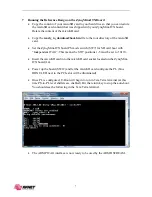
Once PL is configured, U-Boot will begin to run in Tera Term terminal (at this 
time PS-to-PL level shifters are enabled). Hit the return key to stop the auto-boot. 
You should see the following in the Tera Term terminal. 


The ARM PJTAG interface is now ready to be used by the ARM DSTREAM. 


Содержание Zynq Mini-ITX

Страница 1: ...Avnet Zynq Mini ITX Development Board ARM PJTAG Interface Version 1 0 August 2015 ...

Страница 2: ... reference design will require the following software and hardware setups 2 1 Software The software requirements for this reference design are Xilinx Vivado 2015 2 2 2 Hardware The hardware setup for this reference design is Computer with 4 GB RAM and 1 GB virtual memory recommended Avnet Zynq Mini ITX Development Board Power supply Module ATX power supply USB A mini B cable ARM DSTREAM Debug Adap...

Страница 3: ...is connected to the Zynq PL pins referred to as EMIO pins So prior to connecting the ARM DSTREAM debug adapter to the Zynq Mini ITX board a design that connects the ARM PJTAG port to the ARM processor via the PL pins must be must be loaded in to the Zynq device This reference design implements the connection of the ARM PJTAG port to the ARM processor via the PL pins Users can use the steps taken i...

Страница 4: ...ot already installed install the power module onto the Mini ITX board via J8 J9 and J10 connectors 6 Connect the ATX power supply to P2 connector 7 Connect the ARM DSTREAM adapter to the Mini ITX PJTAG header J11 8 Start a Tera Term session and set the serial port parameters to 115200 baud rate 8 bits 1 stop bit no parity and no flow control please refer to the Setting up the Host PC section at th...

Страница 5: ...Vivado IPI GUI should look as shown in the following figure Note If you are using a Windows PC and encounter Windows 260 character path limit issue when trying to rebuild the hardware platform in Vivado the hardware platform is already built for you please refer to the Xilinx Answer Record 52787 to resolve the issue http www xilinx com support answers 52787 htm In addition to the above Answer Reco...

Страница 6: ...esign to open the PS Configurator Click on the MIO Configuration and noticed that the PJTAG box is checked and PJTAG interface I Os are mapped to the EMIO pins I Os pins in the Zynq PL Click Cancel to continue Double click on the system xdc file to open it ...

Страница 7: ...mmable Logic PL EMIO pins The ready_to_download folder contains files that are needed to boot the Zynq Mini ITX board and enable the ARM PJTAG connections The ready_to_download folder contains the following files o Zynq Mini ITX board FSBL ELF file generated by exporting the reference design Vivado project to SDK o PL bitstream to connect the PJTAG signals to the PL EMIO pins bitstream is generate...

Страница 8: ...or SD card boot with Independent JTAG This means the SW7 positions 1 5 must be set to 10110 Insert the microSD card into the microSD card socket located on the Zynq Mini ITX board J4 Power up the board SW12 and let the microSD card configure the PL blue DONE LED next to the PCIe slot will be illuminated Once PL is configured U Boot will begin to run in Tera Term terminal at this time PS to PL leve...

Страница 9: ...8 2 Configure the Host Computer COM Port The Reference design uses a terminal program to communicate between the host computer and the Mini ITX board To configure the host computer COM port for this purpose 1 Connect the Mini ITX board to the host computer via the J7 USB UART port and power up the board 2 Open the host computer Device Manage as shown in the following figure In the Windows task bar...

Страница 10: ...es shown in the following figure Click on the Advanced button to continue 115200 8 None 1 None 5 Select an unused COM Port Number and then click OK The following figure shows COM1 as the selected COM port number 6 Click OK in the properties window close the Device Manager and the Control Panel ...

Страница 11: ...mputer TeraTerm Pro is available for download at http ttssh2 sourceforge jp index html en To communicate with the Mini ITX board configure the New Connection and Serial Port settings as shown in the following figure These settings must match the host computer COM port settings shown in the previous section ...

Отзывы: