


RFSoC Development Kit Getting Started Guide
Page 20
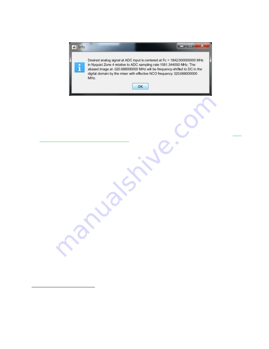
Observe the information dialog confirming the 'effective’ NCO frequency. Refer also to Figure 14.
Each of the RF-ADCs in the Zynq Ult RFSoC is built on multiple sub-ADCs in an interleaving
architecture. The nature of the interleaving process requires that an intricate calibration algorithm be carried
out to obtain the best dynamic range performance from the RF-ADC. It is recommended to remove all signal
power at the input of the RF-ADC during the calibration process; this was accomplished by disabling the TX
signal chain in previous steps. Further details are provided in section ‘
RF-ADC Nyquist Zone Operation’
Ult RFSoC RF Data Converter 2.1 PG269
.
RFSoC Explorer automatically calculates and displays Nyquist Zone and Calibration Mode as a function of the
input signal center frequency Analog Fc, and the ADC tile sampling rate.
Finally set decimation to 8X. This will enable the cascade of 3 half-band decimation filters within the RF-ADC
tile to attenuate unwanted frequency components above 67 MHz (at baseband) and reduce the sampling
rate to 135.168 MSPS.
5
Activate the ‘Configure’ pushbutton to perform ADC calibration and download settings to the RF-ADC tile.
5
This sampling rate is sufficient for the purpose of demonstrating acquisition on a CW tone. In a true PA
linearization application it would be necessary to conserve greater excess bandwidth through the observation
path to capture any non-linear distortion products from the PA beyond the signal bandwidth. The useable
bandwidth through the BAW filter in the DPD observation path is approximately 180 MHz, from 1750 to 1930
MHz.


