


Loom Manual
Page 11
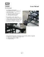
Installation and Commissioning
Personnel:
Installation and commissioning shall be performed by authorized AVL Looms personnel only.
Location:
Equipment must be installed on a flat concrete floor. The concrete floor must be rated to support
a minimum of 2,500 PSI compressive strength.
A 5ft (1.5m) clearance should be provided on each side of loom. Space considerations for the
customer-supplied creel will include the at least 5ft (1.5m) of open space between the back of the
loom and the creel, plus the creel length.
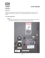
Connection to Plant Electrical:
Connection of the equipment to electricity shall be performed by a qualified electrician only. The
plant circuit must be rated for 208-240 VAC, 50-60Hz, single phase with line 1 at 20A and line 2
at 15A. The electrical cord provided may be either hardwired into the plant electricity or wired to
a suitably rated plug for a corresponding outlet.
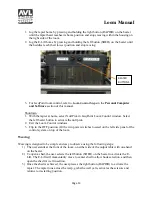
Seismic Concerns:
Where seismic concerns exist, equipment should be installed with supplied brackets and
hardware. Use HILTI drop in expansion anchors inserted into the concrete floor. Use HILTI
instructions for concrete preparation and anchor installation. Use Grade 5 ½”-13x1” Fastener
Bolts (or equivalent metric hardware).
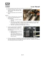
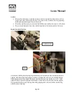
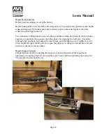
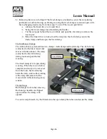
Loom Square and Level
The loom must be squared and leveled during installation. Squaring entails measuring
diagonally, front to back, in each direction. If the measurements do not match within one-
sixteenth of an inch, loom hardware is loosened and the frame is racked until the measurements
match, then the frame hardware is tightened. The loom is provided with six adjustable height feet
for leveling. For side to side leveling, place a level on a horizontal crossmember and adjust the
feet. For front to back leveling, place a level on a horizontal sideframe member and adjust the
feet. Feet adjustment may require slight jacking of the frame.
Содержание TECHNICAL EDUCATION LOOM
Страница 27: ...Loom Manual Page 27 Cloth Clamp Closed Cloth Clamp Open Fixed Clamp Open Fixed Clamp Hanging ...
Страница 29: ...Loom Manual Page 29 Module Hooks Exposed Front Cover Removed Hooks Close Up ...
Страница 33: ...Appendices Page 33 APPENDIX A WIRING DIAGRAMS continued ...
Страница 34: ...Appendices Page 34 APPENDIX A WIRING DIAGRAMS continued ...
Страница 35: ...Appendices Page 35 APPENDIX A WIRING DIAGRAMS continued ...
Страница 36: ...Appendices Page 36 APPENDIX A WIRING DIAGRAMS continued ...
Страница 37: ...Appendices Page 37 APPENDIX A WIRING DIAGRAMS continued ...
Страница 38: ...Appendices Page 38 APPENDIX A WIRING DIAGRAMS continued ...
Страница 39: ...Appendices Page 39 APPENDIX A WIRING DIAGRAMS continued ...
Страница 40: ...Appendices Page 40 APPENDIX A WIRING DIAGRAMS continued ...
Страница 41: ...Appendices Page 41 APPENDIX A WIRING DIAGRAMS continued ...
Страница 42: ...Appendices Page 42 APPENDIX A WIRING DIAGRAMS continued ...
Страница 43: ...Appendices Page 43 APPENDIX A WIRING DIAGRAMS continued ...
Страница 44: ...Appendices Page 44 APPENDIX A WIRING DIAGRAMS continued ...
Страница 45: ...Appendices Page 45 APPENDIX A WIRING DIAGRAMS continued ...
Страница 46: ...Appendices Page 46 APPENDIX A WIRING DIAGRAMS continued ...
Страница 47: ...Appendices Page 47 APPENDIX A WIRING DIAGRAMS continued ...
Страница 48: ...Appendices Page 48 APPENDIX A WIRING DIAGRAMS continued ...
Страница 49: ...Appendices Page 49 APPENDIX A WIRING DIAGRAMS continued ...
Страница 50: ...Appendices Page 50 APPENDIX A WIRING DIAGRAMS continued ...
Страница 51: ...Appendices Page 51 APPENDIX A WIRING DIAGRAMS continued ...
Страница 52: ...Appendices Page 52 APPENDIX A WIRING DIAGRAMS continued ...
Страница 53: ...Appendices Page 53 APPENDIX A WIRING DIAGRAMS continued ...
Страница 54: ...Appendices Page 54 APPENDIX A WIRING DIAGRAMS continued ...


