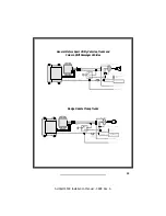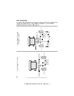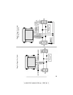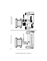
Remote Start Armed Signal (-) Output
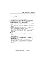
The GRAY/BLACK wire will provide a continual ground output for as long as
the vehicle is in the remote start mode. This output can be used for additional
ignition, starter or heater/AC relays.
Siren/Horn (-) Output (Remote Panic Capability)
The VIOLET wire will provide (-) output when the LOCK button is pressed for
3-4 seconds. The (-) output can be programmed for a continual output when
adding an optional siren or a pulsed output when tapping into the vehicle (-)
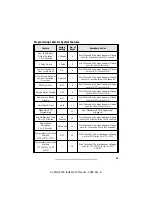
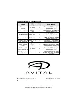
horn wire. See the "Programming Table for System Features" on page 21.
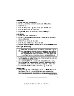
Factory Alarm Disarm (-) Output
The GRAY/WHITE wire will provide a 0.75 second ground output when the
START button is pressed.
1. Arm the vehicle factory alarm system.
2. Use a volt/ohmmeter to locate the one wire that will show ground only
when the driver door key cylinder is held in the unlock position.
NOTE: Most factory alarm/disarm wires will show 8-12 volts while
armed. A few vehicle disarm wires will rest at a neutral state while
armed. Regardless of type, both types will change to ground when the
key cylinder is turned to unlock.
3. Connect the GRAY/WHITE wire to the factory alarm disarm wire.
Accessory Remote Start (-) Input
The BLUE/ORANGE wire will accept a (-) input pulse to activate the remote
start.
Ignition Switch Connections
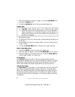
NOTE: Because these wires can draw high current, we recommend that they
be soldered and shrink tubed or taped. If only one PINK wire is needed, tape
the end of the second PINK wire to prevent a short circuit. The main control
module has an 18 ga PINK wire that must be connected to the vehicle
ignition wire with one of the satellite module 14 ga wires.
9
AviStart 4500 Installation Manual - 0898 Rev. A
Содержание AviStart 4500
Страница 1: ...AviStart 4500 Installation Manual 0898 Rev A ...
Страница 2: ...AviStart 4500 Installation Manual 0898 Rev A ...
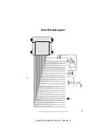
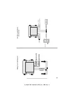
Страница 5: ...3 AviStart 4500 Installation Manual 0898 Rev A Main Wiring Diagram ...
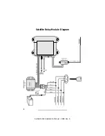
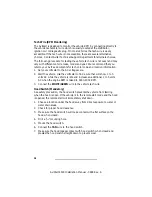
Страница 6: ...4 AviStart 4500 Installation Manual 0898 Rev A Satellite Relay Module Diagram ...
Страница 17: ...15 AviStart 4500 Installation Manual 0898 Rev A ...
Страница 18: ...16 AviStart 4500 Installation Manual 0898 Rev A ...
Страница 19: ...17 AviStart 4500 Installation Manual 0898 Rev A ...


