background image

6

7

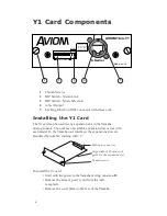
expansion port to expose the expansion connections.

• Remove the Y1 card from its protective anti-static 

sleeve.

• Slide the Y1 card into place, aligning the sides of  the 

card with the support guides in the expansion slot.

• Press the Y1 card firmly in place to attach the multi-pin 

card connectors on the Y1 card and Yamaha mixer.

• Attach the Y1 card permanently by tightening the two 

thumb screws on the rear panel of the Y1 card.

N

OTE

: Aviom suggests using Category 5e (or better) cables when 

making A-Net connections.

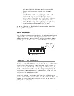
DIP Switch

The 10-position DIP switch provides two separate functions. The first 

eight switches are used for controlling the stereo link status of the 

eight possible audio channel pairs. The last two switches (labeled 9 

and 10)  provide mode selection control for the Y1 card operation.


������ ����

����

��

Stereo Link Switches 

Positions 1 to 8 of the DIP switch are used for the stereo link function. 

Stereo linking is possible when using Aviom’s Personal Mixers for 

stereo monitoring. Each switch controls a pair of channels; see the 

list below. When the switch is set to the “On” position (down),  the 

channels are linked as a stereo pair. If the switch is in the “Off “ (up) 

position, the channels are not linked.

Stereo link changes can be made at any time. All connected A-Net 

devices will instantly update and reflect the change. Compatible A-Net 

devices that do not respond to stereo linking will not be affected by 

changes to the link status. 

���� �� ���

������������

����� ���

������ ����

����

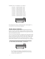
Dn/Up - Aviom

Up/Dn - 16 ch

Up/Up - 8 ch

Dn/Dn - Test

��

Содержание AVIOM16/O-Y1

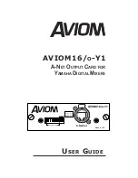
Страница 1: ...AVIOM16 O Y1 USER GUIDE A NET OUTPUT CARD FOR YAMAHA DIGITAL MIXERS Dn Up Aviom Up Dn 16 ch Up Up 8 ch Dn Dn Test...

Страница 2: ...t failure You must turn off the power of your device before you begin installing the AVIOM16 o Y1 card Be sure to disconnect the power cable from the main unit before installing this card to eliminate...

Страница 3: ...ent generates uses and can radiate radio frequency energy and if not installed and used in accordance with the instructions may cause harmful interference to radio communications However there is no g...

Страница 4: ...el operation Test mode The Y1 card is designed to be electrically and mechanically com patible with any Yamaha mixing board product that supports the mini YGDAI card hardware specification Consult the...

Страница 5: ...pansion slot in the Yamaha mixing console The number of available expansion slots varies with each model In the Yamaha user interface the expansions slots are identified by number starting with 1 To i...

Страница 6: ...e stereo link status of the eight possible audio channel pairs The last two switches labeled 9 and 10 provide mode selection control for the Y1 card operation Stereo Link Switches Positions 1 to 8 of...

Страница 7: ...nd 10 of the DIP switch are used for card mode selection There are four possible switch combinations three operational modes and one test mode are provided The Y1 card is scanned during the Yamaha con...

Страница 8: ...16 channel capability mode The Yamaha console recognizes the Y1 card as a generic 16 channel expansion card Names in text fields will display with a generic name such as ADAT 16 depending on the mode...

Страница 9: ...oubleshooting using the Y1 card Test Mode if the 1kHz test tones are heard in channels 1 through 4 of a connected A Net device this indicates that the Y1 card is operating properly Check the channel r...

Отзывы: