background image


Map Pages

    3-3


North Up can be either Magnetic North or True North depending 
on the “Bearing Reference” selection on the User Options – 
SETUP tab of the AUX page. 

 
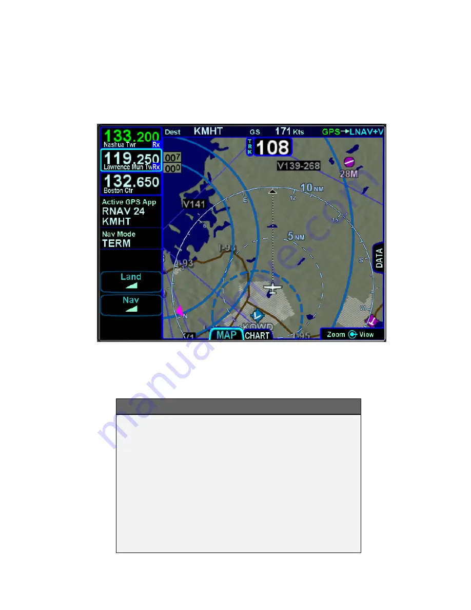
Track-Up, Arc View Example   


TIPS AND TECHNIQUES 

Map Content Control                                            


Map features displayed are highly dependent on a 
combination of the map view, map range, map 
declutter settings, and user setup choices. For 
example, if the flight plan concludes at an airfield, 
the airfield identifier may be automatically 
decluttered in favor of the waypoint identifier that 
represents the airfield from the flight plan.  In this 
example, both identifiers can be made visible by 
ranging in the map to under 4nm. 

Содержание IFD540

Страница 1: ......

Страница 2: ......

Страница 3: ...nt that coincided with Software Release 10 1 0 0 01 July 2015 Optimizations for black and white printing 02 November 2015 Corrected several errors and added some additional descriptions 03 May 2016 Update to accompany Software Release 10 2 0 0 Change bars reflect changed text from the previous revision ...

Страница 4: ...s 1 43 WAAS vs Non WAAS Operations 1 44 Interaction with External Devices 1 45 Before Takeoff Techniques 1 46 2 FMS Pages 2 1 FPL FLIGHT PLAN TAB 2 1 FMS Basic concepts 2 1 Creating A New Flight Plan 2 3 Selecting a Departure 2 8 Saving Naming A Flight Plan 2 11 Activating A Flight Plan 2 12 Copying A Flight Plan 2 12 Inverting A Flight Plan 2 12 Preview Flight Plans 2 12 Modifying A Flight Plan 2...

Страница 5: ...nning 3 10 Graphical Flight Planning Rubber Banding 3 11 Altitude Constraints on Map 3 13 Map Information Pop Up Boxes 3 14 Datalink Weather Overlays and Operations 3 16 Datalink RADAR 3 17 Weather Overlays on Map 3 19 TFRs 3 23 Indications of Data Age 3 24 Weather Radar Selection for Map Overlay 3 25 Terrain 3 27 Terrain Awareness TA 3 27 Forward Looking Terrain Alerting FLTA 3 29 500 Callout 3 3...

Страница 6: ...AVIGATION MODE CDI SCALE CHANGING 5 18 APPROACH PROCEDURES 5 19 Precision Approaches 5 21 Non Precision Approaches 5 21 Back Course Approaches 5 22 Procedure Turns and holds in Lieu of Procedure turns 5 22 WAAS Approaches 5 23 MISSED APPROACH 5 27 RETRY APPROACH 5 29 RNP RNAV OPERATIONS 5 30 6 General 6 1 CAUTION ADVISORY SYSTEM CAS ALERTS 6 1 Master Caution Lamps 6 1 Warning Caution Advisory Mess...

Страница 7: ...ATA BACKUP RESTORATION PROCEDURE 6 41 Saving User Data 6 41 Reloading Previously Stored User Data 6 43 DATALOGS DOWNLOAD 6 44 SOFTWARE UPDATES 6 48 HIGH TEMPERATURE OPERATIONS 6 48 COLD TEMPERATURE OPERATIONS 6 49 LOW POWER OPERATIONS 6 49 HIGH POWER OPERATIONS 6 50 CHARGING FROM THE USB 6 51 PLUG AND PLAY DETAILS 6 52 CLEANING THE DISPLAY 6 54 PAIRING A BLUETOOTH KEYBOARD 6 55 SELF TEST OUTPUT 6 ...

Страница 8: ......

Страница 9: ...ertain situations or areas of operation having heightened safety implications While it is important for the operator to be familiar with all of the information in the manual it is essential to the safe use of the IFD540 that pilots give careful attention to the material contained within these NOTEs In order to avoid a diversion of attention from the task of safely taxiing pilots should avoid perfo...

Страница 10: ... and electronic charts and checklists along with a number of timer and calculator types of utilities and options for weather radar control and display and a video display The system includes terrain alerting as well as an option for TAWS FUNCTIONAL OVERVIEW The Avidyne IFD540 Integrated Flight Display IFD system supports the following functions Flight Management System FMS WAAS and non WAAS GPS Na...

Страница 11: ...touch touch screen technology meaning that features such as two fingered pinch zoom for range changing on maps and charts is fully enabled The system has been designed for single pilot IFR operation and features a Page and Tab user interface Most functions revolve around the three Page Function Keys that appear across the bottom edge of the bezel Each of the three functional pages has associated t...

Страница 12: ...e tabs Page Function Keys and Tabs LINE SELECT KEYS Line Select Keys typically abbreviated to LSK in this manual are the buttons found along the left vertical side of the bezel These are different from Page Function Keys in that they also have a label just inside the bezel adjacent to the physical LSK which indicates the function of the LSK Pressing the LSK or touching the LSK label on the display...

Страница 13: ...the inner ring is fine control and the outer ring is coarse control of that function The symbol used to represent the right knob is a ring with a center dot Right Knob Label Scheme In the example above the outer ring scrolls through a list in a coarse manner and the inner ring scrolls through the same list stopping at each minor field along the way Pushing the knob generates a drop down menu State...

Страница 14: ...unction Keys Green Active White Available but not currently active Note AUX can also be Red Yellow or Cyan if there is an active alert as described later in this manual FMS Fly To Data e g active leg of flight plan To Waypoint datablock Magenta Active Nav Data e g Active Com freq Active Nav freq Active Nav Source mode Green Line Select Key Labels Light Green Line Select Key States White ...

Страница 15: ...the unit was designed to be plug and play compatible with a Garmin 530 W unit BEZEL LAYOUT Starting in the top left corner and working counter clockwise around the bezel the IFD540 has Power Volume Squelch knob Volume Power Squelch Knob Frequency Swap USB Port Line Select Keys LSKs Com Nav Manual Tuning Knob Page Function Keys Cam Latch Context Sensitive IFD Knob CDI Nav Source Knob Ambient Light ...

Страница 16: ...ge Function keys along the bottom FMS MAP AUX Mechanical Cam Latch control for tray installation Dual Concentric Rotary Knob that is page dependent Six 6 Dedicated Function Keys consisting of o Direct To D o Procedure PROC o Nearest NRST o Frequency List FREQ o Enter ENTR o Clear CLR Ambient Light Sensor CDI Nav Source knob COOL FEATURE Integrated WiFi Bluetooth The IFD has an integrated WiFi Blue...

Страница 17: ...tically start when the aircraft bus power is applied The power button can be used to turn the unit off press and hold and watch 5 second count down expire or to turn the unit back on if it had been manually turned off Manual Power Down After power application the bezel keys backlighting will be turned on Several seconds later the IFD display will begin to have indications ...

Страница 18: ...ponse to the ambient light sensor that is embedded in the bezel The user accessible controls for all are on the AUX page using the User Options LSK of the Setup tab Brightness Controls Depending on how the installer configured the brightness controls at time of installation the Auto setting will typically revert to the dimming bus setting in low ambient light conditions If the IFD540 appears inope...

Страница 19: ...ne does not recommend operating with expired databases but the system will allow operation by pressing the Proceed followed by the Confirm LSKs If the IFD has been enabled for Bluetooth and WiFi and either has been configured On on the User Options page then the IFD will present an Allow Ignore page to allow external data receipt via Bluetooth and or WiFi Press the Allow button if such input is de...

Страница 20: ...th fuel totalizers this may result in some fuel display changes on the Fuel Mgmt tab during that period including prompting the pilot to enter in initial fuel That should resolve itself within a few seconds Another example concerns the FMS nav database initialization In this case the message Please wait System Initializing may be displayed on the FPL tab for 10 30 seconds Additionally if the unit ...

Страница 21: ...f when a fix is acquired If the message does not remove itself by the time you are ready to taxi it is a clear indication that your system has not determined its initial position and action may be required on your part TIPS AND TECHNIQUES Bluetooth Initialization Period The Bluetooth keyboard may experience a 1 2 minute delay during post start initialization before becoming functional Depending on...

Страница 22: ...en 14 and 21 Days Old i e up to a week out of date Update Available Next Cycle Date Light Green Charts Issue Date Older Than 21 Days i e more than a week out of date Update Required Date of Expiration Yellow Invalid Type Database Invalid Yellow NOTE Use of Not Yet Effective Data If attempting to use not yet effective data e g charts or nav it is the responsibility of the pilot in command to verify...

Страница 23: ...Use a combination of the page function keys FMS MAP AUX and the associated tabs to change the contents of the rest of the display Each page has a number of associated tabs Each Page Function key has a left and right rocker nature to it Select the page of interest by pressing the middle of the Page Function key and Top strip datablock area Nav Source Label Configurable Data Strip Page Tabs Context ...

Страница 24: ... can display a data strip along the right edge of the display The FPL tab and NRST tab on the FMS page and the Map tab on the MAP page are prime examples In the cases where this is available a labeled side tab is displayed That extra data strip can be pulled out for display or pushed back in for hiding by using any of the following methods Touch the side tab shown in gray boxes below Use a left or...

Страница 25: ...is two com frequencies active and 1 standby above two nav frequencies active and 1 standby A custom display format can be set up to display the active com and up to four standby com frequencies The frequency that will be swapped into the active frequency when the bezel Frequency Swap button is pressed is called the 1 Standby For example in the case where the user has set up 4 com slots to be displ...

Страница 26: ...Delivery Ground Tower Approach etc for the Active and each displayed Standby com frequency are displayed in each com frequency slot This is a handy reminder of the agency to which you have tuned in each slot Similarly if the frequency displayed is a nav frequency then the Morse code decoded identifier will be displayed and will stay displayed for as long as the IFD can decode the Morse code which ...

Страница 27: ...udio to the audio panel for audio monitoring This permits the pilot to monitor a 2 nd com channel e g ATIS while still connected to the active com channel Tuning Tuning can be accomplished through several methods Whichever frequency slot has been selected as the 1 Standby can be manually tuned by twisting the bottom left knob on the bezel The outer ring changes the digits to the left of the decima...

Страница 28: ...y e g GDM for the Gardner VOR via the alphanumeric virtual keypad An automatic geographic based prediction algorithm geofill is running such that the most likely VOR station is filled in based on your geographic position Manual Entry of VOR Identifier A more automated way to tune a com frequency is to press the FREQ button along the right edge of the bezel This will present a list of likely freque...

Страница 29: ...uencies following 20 seconds of inactivity on the Nav frequency display If the IFD is configured for an optional remote transponder then the push action of the lower left knob will toggle between Com frequencies Nav frequencies Transponder tuning then back to Com frequencies Invalid Frequency Entry Attempt Attempting to type an invalid frequency e g typing a nav freq in a com slot will produce a t...

Страница 30: ...the destination airport Enroute the most likely enroute ARTCC up to 50 entries out to 200nm from present position and other enroute com frequencies e g FSS for the current geographic position Recent a running list of the most recent 10 com frequencies that had been selected for the Active frequency slot across power cycles Freq List Page Each additional press of the FREQ function key will cycle to...

Страница 31: ... the 1 standby position Stuck Mic If the IFD determines that there is a stuck mic situation defined as 30 seconds or more of continuous transmission a Stuck Mic CAS message Blue Advisory message will be displayed Remote Tuning Control and Frequency Swapping The IFD supports a host of remote tuning and frequency swapping capability A Com Presets LSK will be present on the AUDIO tab of the AUX page ...

Страница 32: ... Swap control e g dedicated button on the yoke Pressing and holding the dedicated Frequency Swap control button for approximately 3 seconds will insert 121 5 kHz into the Active com slot Other remote tuning and frequency swapping capability is present when dedicated third party radio control display units are wired into the aircraft Usually in these cases when the radio control display unit is act...

Страница 33: ...to communicate with a remote transponder then code and mode control and display is available Display The transponder mode and code is displayed in a datablock that can be configured to be displayed along the left right or top sides of the display Typical Transponder Datablock Locations ...

Страница 34: ...d Nav frequencies and Transponder keyboard The displayed set of Com Nav Xndr data slots will always time out back to com frequencies following 20 seconds of inactivity on the Nav frequency display or transponder keyboard Cycling between Com Nav Transponder Display Touching any of the displayed transponder mode code datablocks will generate the transponder keyboard Transponder Keyboard ...

Страница 35: ...nob is pressed Some aircraft may even been equipped with an optional external IDENT switch e g on yoke Transponder Mode Descriptions and Entry Mode S transponders have the following modes each represented by its own mode key on the transponder keyboard ALT The transponder will respond to all interrogations ON The transponder will respond to all interrogations but altitude reporting is suppressed G...

Страница 36: ...help visually confirm the value being entered When using the bezel knob entry method first ensure the transponder mode code data is displayed in the top left corner of the display by pressing the bottom left knob twice then twist the outer ring of the bottom left knob to adjust the first two digits and twist the inner ring of the bottom left knob to adjust the second two digits All new code entrie...

Страница 37: ...nder is in an active Reply state Transponder Configuration Some typical pilot actions for configuration e g Flight ID definition and default VFR code definition are accessed through the User Options sub page on the AUX page The rest are accomplished via the installer in Maintenance Mode If the IFD is unable to communicate with the remote transponder an associated CAS message is displayed and the t...

Страница 38: ... function key along the right edge of the bezel twice Direct To Enter Enter or touch the Activate dialog box that pops up on the display to accept If a different waypoint is desired there are a number of ways in which the proper waypoint can be entered in that Direct To dialog box Twist the outer ring of the bottom right IFD knob to scroll up down through a flight plan list that re populates the w...

Страница 39: ...d press Enter on the keypad or bezel to accept Twist the inner ring of the lower right IFD knob while the pop up green Direct To dialog box is displayed to go into edit mode The inner ring changes the character and the outer ring changes the cursor position in the waypoint name field It may not be necessary to fill in all letters of the waypoint name since they will auto fill When the desired wayp...

Страница 40: ...nearest list to another category as defined in the list below o Nearest Airports o Nearest Airports to Destination o Nearest VORs o Nearest NDBs o Nearest Intersections o Nearest ARTCCs o Nearest FSS o Nearest Airspace o Nearest User Waypoints Procedure The PROC function key acts as a shortcut for attaching a published arrival or approach procedure to a waypoint in your flight plan It can be used ...

Страница 41: ...ended data field twist the bottom right IFD knob to scroll up or down the list until the desired procedure is highlighted and then push the knob in to add that procedure to the flight plan If there is no flight plan pressing the PROC key will present the FPL tab with an insert cursor at the top of the page but will not present any procedures Enter The use can vary slightly depending on the scenari...

Страница 42: ...s useful during turbulent or bumpy flight conditions where it is often very difficult to precisely and reliably touch the desired point on the display Having a physical bezel control provides an anchor point or control to hold on to and exercise the intended action TIPS AND TECHNIQUES User Control to Turn Touch Off The User Options LSK on the SETUP tab of the AUX page provides a touch screen on of...

Страница 43: ...ys e g changing the major pages of FMS MAP AUX Map panning Power on off Graphical Flight Planning Rubber banding Changing the Primary Nav Source Calling up a map page info box Starting the Frequency List Selecting a 2 or 3 standby frequency for swapping into the active frequency slot Frequency Swap Changing transponder mode ...

Страница 44: ...oint data or nav com frequencies using touch virtual keyboards are displayed on the IFD There are two formats a numeric keyboard and an alpha keyboard with a means to switch back and forth between formats Virtual Alpha Keyboard Virtual Numeric Keyboard ...

Страница 45: ...tating the entry is invalid Validity logic is not applied on cross side keyboards in dual IFD installations Invalid Keyboard Entry Alert TIPS AND TECHNIQUES Optimal Touch Performance To maximize touch performance the more surface area of a finger that can make contact with the glass the better Try to avoid using just fingernail contact or just the tip of a finger Increased pressure on the glass by...

Страница 46: ...uencies etc the paired external keyboard can be used instead COOL FEATURE Convenient Data Entry If air is turbulent or touch is turned off or physical access to the controls is difficult an external keyboard can be an easier way to enter data on the IFD NOTE Dual IFD Installations Should Only Pair 1 IFD To avoid issues arising from a keyboard only being able to pair with one device at a time dual ...

Страница 47: ... The lightbulb key turns on backlighting for the keyboard The vertical two headed arrow key is primary 1 standby swap The Avidyne logo key is a space bar The up down arrow keys can be used for page navigation in the same way the inner and outer rings of the bottom right IFD knob can navigate through page fields Repeated presses of the FMS MAP AUX keys step through the tabs on those pages Avidyne S...

Страница 48: ...ons LSK of the SETUP tab on the AUX page the second IFD will automatically present a virtual keyboard when the other IFD is in a mode where data is being entered or edited In other words if Keyboard Convenience mode is turned on a virtual keyboard will be displayed on the other IFD at all the same times as if the aircraft were configured for a single IFD and a keyboard is displayed on that unit Sh...

Страница 49: ...eed to have the same WAAS antenna configuration either both are WAAS or both are non WAAS If one IFD is set up with a WAAS antenna and one is set up with a non WAAS antenna then the FMS related data flight plans waypoints routes will not be shared between IFDs NOTE Dissimilar Weather Traffic Source Data Not Shared Dissimilar weather data sources e g GDL 69 data on one IFD and MLB100 data on the ot...

Страница 50: ...lections therefore no cross side tuning or display Nav deviation data therefore no navigation miscompare alerts are provided Local CAS alerts Datablock configuration Chart displayed Electronic Checklists data and state Calculators and Utilities data NOTE Data Sharing Tolerates Inconsistent Databases While Avidyne strongly recommends the databases on each IFD be kept up to date and on the same cycl...

Страница 51: ...pproach and transition data streaming from IFD to 3 rd party application to allow automatic approach chart selection and display on the 3 rd party application Traffic data streaming from IFD to 3 rd party application for display on the 3 rd party application Weather data streaming from IFD to 3 rd party application for display on the 3 rd party application Flight plan route data transmitted by the...

Страница 52: ...he IFD supports both WAAS and non WAAS operations In each case the IFD is still considered a G system for flight plan filing purposes When configured to be connected to an approved WAAS antenna at installation the IFD serves as a fully certified WAAS GPS navigator Published WAAS procedures will be available and presented in the various drop down list choices in the FMS and WAAS glideslopes will be...

Страница 53: ...approved for integration with all equipment the GNS 530 is approved for plus the IFD is approved for integration with additional equipment beyond those authorized for use with the GNS system TIPS AND TECHNIEQUES Dual IFD Installations Should Only Use 1 WiFi For reliable WiFi operations Avidyne recommends turning off WiFi from the User Options page on one of the IFDs NOTE Shared Data Between IFD540...

Страница 54: ...d datablock selections to ensure set up for your personal preferences Avidyne recommends creating and using the Checklist utility and including a Before Takeoff checklist that meets your personal needs TIPS AND TECHNIEQUES Avoid The Use of Polarized Sunglasses Avidyne recommends avoiding using polarized sunglasses when using the IFD due to likely washing out of colors and apparent dimming ...

Страница 55: ... Centric Calculations The FMS presumes there is intent to fly the flight plan as created All deviation data most data block data and the times to go and fuel calculations are all based on that assumption Each leg of a flight plan has its own color coded background designed to make the overall flight plan easier to read at a glance Each flight plan can consist of up to 128 legs The origin and all a...

Страница 56: ... the IFD to see the visual difference The insert cursor will appear as a thin blue horizontal line that appears between flight plan legs This allows you to insert new legs The edit cursor appears as a wrap around blue box that encircles the entire leg and allows you to edit an existing leg Insert Cursor Edit Cursor Edit Cursor wrap around blue box ...

Страница 57: ...conds CREATING A NEW FLIGHT PLAN The first time the Flight Plan tab of the FMS page is accessed following power on an empty flight plan page is presented with the origin waypoint pre populated The origin will be the closest airport to the current GPS position or the airport from the previous power down if GPS position has not locked on yet If the origin is not the point you want to start from dele...

Страница 58: ...f the flight plan It indicates where the viewable window is with respect to the entire flight plan as well as where the active leg in the flight plan is In the image above the magenta vertical rectangle in the scroll bar indicates the active leg is just below the origin There are a number of flight plan legs out of sight below the bottom of the display There is an option available to configure the...

Страница 59: ...the desired exit point and then all intermediate intersections along that airway are automatically populated into the flight plan The pictures below are an example of the airway drop down box that is displayed when building a flight plan and then the exit point choices once the airway is chosen Use the bottom right IFD knob to scroll the list for the desired airway and exit point off the airway Th...

Страница 60: ...w every leg of the flight plan Expanded or an abbreviated version of the flight plan Compact via the View LSK The compact view hides all intermediate legs of an airway between the entry and exit point It also hides intermediate legs of published departures arrivals and approaches such as step down fixes The active procedure or airway is always expanded ...

Страница 61: ...dge until the Cursor option is displayed and can serve as a good way to conduct initial planning and later review Once in the view indicated by the annunciation FMS Cursor Centered overlaid on the map the map is centered on the fix surrounded by the FMS cursor As the FMS cursor is scrolled up down the flight plan the map center point changes This allows you to see close up details of the downpath ...

Страница 62: ...gin departure airfield and pushing in that knob Departure Procedure Drop Down List TIPS AND TECHNIQUES Vector Standard Instrument Departure SID Vector or Radar SIDs are not likely to be part of the list of available departures in the FMS dropdown This is due to the nature of the data encoding from the supplier They are however likely to be present in the list of available charts for the departure ...

Страница 63: ...y transitions For those cases the rest of this process is skipped and the selected procedure and enroute transition are inserted into the flight plan Otherwise the FMS proceeds differently based on whether the airport origin for SIDs destination for STARs has a selected runway If the airport has a selected runway and that runway is applicable to the selected SID STAR then the FMS will choose the r...

Страница 64: ...way was not applicable to the SID STAR then the FMS will set the runway for the airport based on the runway transition that was selected There are cases where a runway transition applies to all runways at the airport or to a set of parallel runways In those cases if there was no selected runway for the airport the FMS will select the first runway numerically that is applicable ...

Страница 65: ...wn the route list until the desired flight plan is highlighted by a surround cursor By pushing the knob the selected route will load and the route name field will be shown in reverse video Touch the reverse highlighted name field or push the bottom right IFD knob to generate a virtual keyboard with which to type the desired name To accept the new route name press either the ENTR bezel key or the E...

Страница 66: ...ht plan and edit it as required If no editing is required you have successfully saved or copied a flight plan INVERTING A FLIGHT PLAN From the Route tab of the FMS page use the bottom right knob on the IFD to scroll up or down the list of routes to the desired flight plan or touch the desired route to invert Press the Invert LSK This automatically inverts the flight plan and leaves the route name ...

Страница 67: ...common tasks are described below INSERTING A WAYPOINT From the FPL tab use the bottom right knob on the IFD to scroll up or down the flight plan until the insert cursor is positioned where the new waypoint is to be inserted At that point push the knob to generate a drop down box from the cursor position Scroll up and down in that drop down box until you find the option you seek Press the knob agai...

Страница 68: ...LR button and it will walk up the flight plan deleting earlier waypoints as you go Waypoints can also be deleted by touching the waypoint to be deleted and then selecting the L4 Delete Waypoint LSK NOTE Unable to Delete Published Procedure Waypoint Waypoints that are part of a published procedure departure or arrival may not be deleted EDITING A WAYPOINT From the FPL tab the bottom right knob on t...

Страница 69: ...the knob and enter the desired value or double tap the field to display a virtual keypad This can be accomplished at any time on the ground or in air and are depicted on the map display as well Vertical Constraint Choices Cross Type Altitude Number field selecting distance in NM from waypoint for crossing constraint At Or Below At At or Above Altitude field selecting the target altitude Minimum al...

Страница 70: ... from the active waypoint will be reflected by the To From flag as in a traditional HSI The course deviation indicator will be presented in relation to the selected course As the FMS course is adjusted via the external course set knob or the IFD nav source knob if no external device is installed the active leg on the FPL tab will change to Fly Course xxx as shown in the image below The FMS Course ...

Страница 71: ...DING PATTERN A hold can be put on any waypoint that has a fix terminated leg waypoints that terminate with a lat or lon position such as navaids enroute waypoints user waypoints airports etc Legs that terminate at an altitude DME distance radial crossings etc do not support attaching a hold Hold fixes are always fly over waypoints and not fly by waypoints Use the edit cursor on the flight plan to ...

Страница 72: ...by allowing you to choose the desired or assigned hold pattern course turn direction and leg length time Once a published hold has been inserted when the FMS cursor is on one of the hold parameters the L3 LSK will display Standard Hold Pressing that LSK will change the parameters to be standard right turns 1 min legs and an inbound course matching the course of the leg before the hold If any of th...

Страница 73: ...e SAR Special Use Mission package is active then circular orbits can be added to the plan Circular Orbit Depiction on Map The function is activated by selecting the On choice in the Patterns field on the FMS Setup page Circular Orbit Pattern Selection in FMS Setup ...

Страница 74: ...at is not part of a terminal procedure Select the Orbit waypoint option in the standard FMS insert cursor drop down list The orbit radius can range from 1nm to 20nm The FMS will not actually fly to the orbit fix and instead will fly to the point where the leg to the fix intercepts the orbit Orbit Row in Flight Plan ...

Страница 75: ... plan use the bottom right IFD to scroll as required to create an edit cursor surrounding the holding leg or touch the hold leg to be deleted then press the Delete Hold LSK EDITING A HOLDING PATTERN Position an edit cursor around the holding leg of interest in your flight plan Use the inner ring of the bottom right IFD knob or touch the field to be edited to highlight the desired field e g turn di...

Страница 76: ...defined flight plan the IFD will provide a message about an impending turn that includes the upcoming desired track DTK and a 10 second 30 second if the required turn is more than 120 degrees count down COOL FEATURE Automatic VOR Tuning The FMS will automatically tune the next down path VOR in the active flight plan into the primary nav frequency slot TIPS AND TECHNIQUES Times to Turn Off Automati...

Страница 77: ...Left X X NM To delete a lateral offset press the Delete Offset LSK The maximum offset that can be dialed in is 20 NM Lateral offsets are not available when in OBS mode Lateral offsets are unaffected by graphical route planning rubber banding operations Lateral Offset Map Depiction GAPS OR DISCONTINUITIES IN FLIGHT PLANS A Gap In Route will appear within the flight plan when there is a discontinuit...

Страница 78: ...Connecting Gap in Route Avidyne recommends that you input the arrival and approach for the destination airfield and alternates into the FMS flight plan Selecting a published arrival and or approach will automatically load the procedure including all altitude constraints into the FMS Take advantage of the system to stay ahead of the airplane by using the wind vector datablock selection a constant c...

Страница 79: ... 2nm from the active leg centerline Aircraft course is within 45 degrees of Desired Track DTK The TOD function is not available on any waypoint of an approach past the Final Approach Fix FAF or in holds or procedures turns The FMS uses a default of 500 feet per minute descent rate or as edited in the Preferred Descent Rate field on the FMS Setup page There is an associated tone sounds like a door ...

Страница 80: ...shed altitude If your flight plan contains consecutive approaches and you activate the next approach during climb out from the previous approach and prior to reaching the next approach s FAF altitude this Check Altitude Too Low message may be displayed ENTERING AN ARRIVAL AND APPROACH From the FPL tab use the bottom right knob on the IFD to scroll up or down the flight plan as required until the e...

Страница 81: ...on as changes start to be made to the FMS flight plan while on that tab real time overlays of the edited procedure hold pattern waypoint or airway are presented on the map in cyan There may be a few second delay when drawing the edited route as the system determines the optimum map range for display This feature provides a graphical preview of the edited route before it is officially part of the f...

Страница 82: ...2 28 FMS Pages Approaches Dropdown Box Procedures Brackets ...

Страница 83: ...lowing destination airfields approaches and arrivals in the flight plan and wrap back around to the top of the flight plan When you have the drop down box over the intended field use either the bottom right knob on the IFD or touch the list to scroll up or down the list until the desired procedure is selected then push that knob in to add that procedure to the flight plan If there is no flight pla...

Страница 84: ...D TECHNIQUES Deleting an Approach From Active Flight Plan One of two techniques is recommended to delete a an approach from an active flight plan if you want to replace the approach with another one for the same airfield press the PROC key and select a new approach If you just want to delete the approach altogether scroll the flight plan to the blue airfield leg ensure the cyan highlight in on the...

Страница 85: ...n strip on the right While it can be useful in many phases of flight and scenarios the split page is especially helpful during arrivals This can be most useful to instantly correlate your flight plan with the graphical depiction on the map This aids in error reduction and helps visually see options for diverts weather avoidance etc Map FPL Split Page ...

Страница 86: ...t Extent Box COOL FEATURE Hot Links to Charts in Flight Plan Whenever a flight plan leg blue airfield legs has at least one published approach associated with it a chart icon is presented on the right edge of the flight plan leg By using the right hand knob on the IFD scroll through the flight plan elements until the chart icon is highlighted in reverse video If at that time the knob is pushed in ...

Страница 87: ...viding METAR data to the IFD color METAR flags will be included in the flight plan leg depiction along the right edge This is designed to give you a quick weather reference for the waypoint and or its vicinity The exact station to which that METAR applies is provided via the flag label and may be different than the actual waypoint identifier ...

Страница 88: ...ouch the field to present a virtual keyboard There is also a Paste LSK along the left edge of the IFD that will nominate the currently active leg of the flight plan or the flight plan leg that is highlighted by a wrap around edit cursor or any selected item from the Nearest lists A search function accessible via the Search LSK is also available to help find the name of the facility for which more ...

Страница 89: ...ll highlight the field if necessary second touch nominates it into the 1 standby or by using the bottom right IFD knob to highlight the desired frequency and then push the knob to nominate it into the 1 standby slot Runways identifies the known runways at the airport to include orientation length and width and a thumbnail map of the runways When an individual runway row has been selected via touch...

Страница 90: ...bnail map depiction of the arrival Approaches identifies the published approaches associated with the airport including any identifier and nav frequency and when an individual row has been selected via touch or the bottom right IFD knob it can further expand to provide a thumbnail map depiction of the approach If the nav frequency is selected by touch or by using the bottom right IFD knob it can b...

Страница 91: ...2 37 FMS Pages Four Additional Rows of Weather Data on Info Tab Info Tab Nearby Navaids ...

Страница 92: ...vated via the Activate Route LSK which makes it the active flight plan and displays the flight plan FPL tab Routes Tab As indicated in the above image each stored route will have its own row with the route name on the left and the origin and destination waypoints identified on the right side of the row The Route tab has provisions to Create a new route Name a route Copy a route Invert a route Acti...

Страница 93: ... the keyboard or push the bottom right IFD knob again to accept the new route name As soon as the route name is completed an insert cursor will be presented and any of the previously described methods for creating a flight plan can be used After a flight plan is entered use the Back to Route List LSK to return to the directory of stored routes or press any other Page Function key to move on to oth...

Страница 94: ...be typed into the virtual keyboard or entered by twisting and pushing the bottom right IFD knob When the desired name is complete press the Enter button on the keyboard or press in the IFD knob to exit the naming edit mode TIPS AND TECHNIQUES Saving Altitude Constraints Prior to Release 10 2 0 0 no manually entered altitude constraints were saved The database contains altitude constraints for SIDs...

Страница 95: ...he desired route from the ROUTE tab by either touching the row or using the bottom right IFD knob Once the desired route to be copied is highlighted press the Copy LSK along the left edge of the display Copy Route LSK This will present a copy of the original route that can then be edited as required ...

Страница 96: ...sired route from the ROUTE tab by either touching the row or using the bottom right IFD knob Once the desired route to be copied is highlighted press the Invert LSK along the left edge of the display Invert Route LSK This will create an inverted copy of the original route that can then be edited as required ...

Страница 97: ...ill display the now active route in the FPL tab DELETING A ROUTE To delete an existing route from the stored routes list highlight the desired route from the ROUTE tab by either touching the row or using the bottom right IFD knob Once the desired route to be deleted is highlighted press the CLR function key along the right edge of the display A confirmation dialog box will then be displayed Delete...

Страница 98: ...g a user waypoint from the WPT tab of the FMS page Present Position Press the PPOS LSK to create a waypoint with your current position No further action is required Enter Lat Lon Press the New LSK then press the Format LSK until the Lat Lon option appears and enter in your desired coordinates either by touching the coordinate field and then using the virtual keyboard or by using a combination of t...

Страница 99: ... using a combination of twists and pushes of the bottom right IFD knob to enter the data Press the Enter LSK to create and save that new waypoint Some external EFIS systems e g Bendix King EFS 40 50 Collins Pro Line 21 etc can also create and send user waypoints to the IFD When the waypoint data is received from the external EFIS the IFD will automatically switch to the WPT tab if not already ther...

Страница 100: ...d then use the ENTR button when the green confirm dialog box is displayed or touch the green box DESIGNATING A USER WAYPOINT AS AN AIRFIELD To designate a user waypoint as an airfield the waypoint must be manually named using the following format AIRPORT XXXXXFT where XXXX is the field s elevation and note that the space is critical in naming the point User Waypoint Airfield Naming Example When us...

Страница 101: ...2 47 FMS Pages User Waypoint Airfield Depiction on Map ...

Страница 102: ... Nearest page has two display formats full page Nearest and a split Map Nearest combination Switching between the two formats is accomplished by opening or closing the side tab when on the Nearest page Full Nearest Tab Split Nearest Tab ...

Страница 103: ...in the middle of the row touching the info i or using the bottom right IFD knob to highlight it and then pushing the knob will jump the page to the INFO tab with that facility information displayed For those rows that contain a chart icon on the right side touching the chart icon or using the bottom right IFD knob to highlight it and then pushing the knob will jump the page to the CHART tab on the...

Страница 104: ... and not Nearest VORs TIPS AND TECHNIQUES Emergency Return to Departure Airfield If on departure leg and an emergency return to the departure airfield is deemed necessary the recommended technique is to press the D button on the bezel twist the bottom right IFD knob counter clockwise to pre fill the departure airfield and press ENTR ENTR to make that the active waypoint Then press the PROC key to ...

Страница 105: ...he active FMS flight plan is always overlaid on the map as are any traffic depictions COOL FEATURE Next Leg Depiction on Map While the current leg of the active flight plan is always depicted in magenta on all moving maps we ve added an indication of the next leg using alternating magenta and white stripes This candy cane indication can come in handy during such circumstances as teardrop entries i...

Страница 106: ...o seconds before timing back out to the actual range number when at the two range extremes Pressing the knob cycles through the various map views The map view selected is indicated at the top of the map next to the heading box No indication means Heading Up All other options are labeled next to that heading box Depending on the installation map view options can be Heading Up or Track Up 360 Headin...

Страница 107: ...ol Map features displayed are highly dependent on a combination of the map view map range map declutter settings and user setup choices For example if the flight plan concludes at an airfield the airfield identifier may be automatically decluttered in favor of the waypoint identifier that represents the airfield from the flight plan In this example both identifiers can be made visible by ranging i...

Страница 108: ...od to increase usable map space especially on dual IFD installations where cleaner maps are desired NOTE Map Orientation Without GPS The map orientation will auto switch from track up orientation to north up orientation when GPS is lost Pilots who leave the map orientation in track up during shutdown may notice the map will start up in north up until a GPS position fix is available at which time t...

Страница 109: ...ions where the IFD is receiving heading select aka heading bug data a hollow magenta heading bug is displayed for reference on the inside edge of the map compass rose Projected track line Dashed white line indicating actual track Connects ownship symbol with compass rose Single Low Obstacle 200 AGL up to 1000 AGL blue Grouping of low obstacles 2 or more low obstacles 200 AGL up to 1000 AGL within ...

Страница 110: ...airport soft Towered airport water If runway orientation known they are also depicted on the airfield symbol blue with white runway Non towered airport hard Non towered airport soft Non towered airport water If runway orientation known they are also depicted on the airfield symbol magenta NDB All NDBs in nav database magenta diamond VOR All VORs in nav database blue Intersection All intersections ...

Страница 111: ...C Each boundary of Class C airspace solid magenta Tower Zone estimated Class D Tower zone dashed blue Victor or Jet Airways All Victor and or Jet airways solid blue gray Terrain scale Indicates highest and lowest limits of the terrain in displayed area Legend colors in between these numerics represent terrain elevations Blue obstacle clearance number shows the top of the highest obstacle when grea...

Страница 112: ... of the max range of the aircraft allowing a 45 minute reserve Winds are indirectly taken into account The calculation uses groundspeed to compute the size of the circle and is based on the value of the fuel totalizer The dashed green circle indicates the total maximum range without using the reserve A wider solid green circle indicates the extra range the reserve fuel should provide The circle tu...

Страница 113: ...rting If selected on the User Options page an aural alert Airspace Ahead will be issued when an imminent airspace penetration is anticipated This is designed to happen approximately 5 minutes 30 sec prior to the projected airspace penetration The aural alert will repeat every 10 seconds until the condition is removed or the associated CAS message is acknowledged TIPS AND TECHNIQUES Scenarios for A...

Страница 114: ... Map Declutter Controls MAP PANNING Panning the map is accomplished by dragging a finger along the display in the direction of desired panning When panning away from the ownship depiction a cross hair cursor is displayed and a readout of the bearing and distance from present position to the cross hair cursor position is displayed next to the cross hair cursor The map will snap back to being center...

Страница 115: ...ur finger on the leg for approximately 2 seconds until the leg turns cyan and then without lifting your finger off the display dragging your finger to the desired location When you lift your finger off the display a dialog box is presented on the display for you to choose confirm the new waypoint being created If the new fix is in close proximity to a facility or facilities in the on board navigat...

Страница 116: ...f you don t see the desired leg turn cyan within 2 seconds of placement of your finger on the location try slightly adjusting the placement of the finger that is being used to designate a leg for rubber banding Move your finger slightly in a direction perpendicular to the leg Note that any leg can be rubber banded including the active leg the magenta one unless the leg is part of a published instr...

Страница 117: ...hical indication of the altitude constraint on the map The three types of altitude constraints are At or Below At At or Above Example Depictions of Altitude Constraints The altitude constraint depiction will also appear at the proper geographic position For example if an altitude constraint were defined to be 5nm prior to a waypoint like it is for KGDM in the image above the graphical representati...

Страница 118: ...ation about that hot spot These boxes will time out in 20 seconds and can also be dismissed by tapping somewhere else on the display A few examples are depicted in the images below Note that in every case there is a page count in the bottom right corner of each pop up box For those boxes that indicate more than one page e g VOR co located with an airfield touching the pop up box switches between t...

Страница 119: ...e map info popup box is not in your active flight plan or nearest list there will be approximately a 1 second delay before the METAR page will created This can be avoided by dwelling your finger on the airfield of interest for approximately 1 second or touch the airfield a second time to give the system time to generate the METAR map info popup page NOTE Map Pop Up Boxes Only Via Touch Map pop up ...

Страница 120: ...lability depends on the product and or level of subscription chosen See the IFD product details page on http www avidyne com products ifd540 ifd weather asp for a complete list of supported weather products NOTE Datalink Data Accuracy Avidyne does not control review or edit the information made available by the datalink products and is therefore not responsible for the accuracy or timeliness of th...

Страница 121: ...icting precipitation as seen by multiple ground based weather radar sites The image is color coded to show intensity levels and precipitation types and is overlaid on top of any other map features including terrain alerting Datalink Precipitation Example Weather Data Legend ...

Страница 122: ...alink radar is unavailable in a particular area for any reason hatched lines appear in that area In the mountains and off the coast hatched lines may represent no coverage below 10 000 feet If there are radar returns in that region above 10 000 feet the returns will be displayed as islands of precipitation surrounded by the hatched lines ADS B FIS B radar data coverage areas can be very irregular ...

Страница 123: ... selection per grouping can be made and products selected are indicated by a green lamp The table below represents the possible set of products available Products that are not available due to the device type or subscription level will not be displayed as selectable choices NOTE ADS B FIS B US Weather Radar Data is Coarse When compared to subscription Datalink service data and even ADS B Regional ...

Страница 124: ...aft Avidyne recommends wiring one weather source to one IFD and the other weather source to the second IFD TIPS AND TECHNIQUES Weather Overlays in Single IFD Operations For those installations with a single IFD and more than one type of weather source e g GDL 69 and a MLB100 in the aircraft Avidyne recommends wiring both weather sources to the IFD so that the higher priority weather overlay can di...

Страница 125: ...ike Sensor Cell Sensor Clear Strikes Product not yet displayed if the source is a MLB100 Selections can be made by either touching the desired product or by using the bottom right IFD knob Note that when there is an on board lightning sensor selected Avidyne TWX670 Tactical Weather System or L3 WX500 Stormscope the Lightning grouping will also include a Clear Strikes function key A WX 500 Lightnin...

Страница 126: ...ols that summarize a recent surface weather observation and can appear as overlays on the Map and embedded in the flight plan on the Flight Plan tabs and Nearest tabs These flags allow an overview of general weather conditions in an area Graphical METAR Legend AIRMETs and SIGMETs US only These are areas where the National Weather Service has issued advisories for various types of hazardous weather...

Страница 127: ...Pending TFRs TFR data is also transmitted via Broadcast Datalink Two types of TFRs are depicted active and pending Active TFRs are depicted as solid red lines and Pending TFRs are depicted as dashed red lines which become solid when the TFR transition time rolls from pending to active TFR data cannot be turned off The right edge of each leg in a flight plan presents a METAR flag for the closest re...

Страница 128: ...ayed the icing altitude slice currently displayed is shown in the bottom right corner NOTE Datalink Data Position The in cockpit RADAR display depicts where the weather WAS not where it IS The age indicator does not show the age of the actual weather conditions but rather the age of the mosaic image The actual weather conditions could be up to 15 to 20 minutes OLDER than the age indicated on the d...

Страница 129: ...weather radars is an optional capability for the IFD When this option has been activated on an IFD and if the IFD has access to heading data radar data can also be a selectable overlay on the moving map Onboard Radar Selection on Wx Overlay Onboard Weather Radar Overlay on Map ...

Страница 130: ...rd weather radar from the map page it is simply an on off layer The map can be decluttered to remove non essential map content but still provide map and flight plan graphical situational awareness and a more typical weather radar depiction at the same time Decluttered Map with Onboard Weather Radar Overlay ...

Страница 131: ...nd a 9 arc sec terrain database WGS 84 to display a two dimensional scene representing an exocentric look down from above view The database is loaded on the IFD prior to shipping from the factory and is capable of being updated in the same manner as other onboard databases if necessary Both TA and FLTA compute height above terrain via GPS inputs and are not a radio altimeter RADALT TERRAIN AWARENE...

Страница 132: ... inside a 3nm radius of the aircraft position and whose top is between 100 below aircraft altitude and 1000 below aircraft altitude will generate a yellow threat bubble over the obstacle Obstacles inside a 1 5nm radius of the aircraft position and whose top is between 100 below aircraft to anything above aircraft altitude will generate a red threat bubble over the obstacle TA can be turned off via...

Страница 133: ...ance between the aircraft flight path and nearby terrain or obstacles falls below a designated safe vertical distance The reduced terrain and obstacle clearance distance varies with phase of flight and aircraft dynamics per TAWS TSO C 151c TSO C 194 for helicopters but generally ranges from 300 to 1000 100 to 150 for helicopters Either terrain or obstacles can trigger FLTA alerts and they are dist...

Страница 134: ...wever the CAS visual alerts and associated aural alerting will only honor the highest priority alert The priority order is Terrain Warning Obstacle Warning Terrain Caution Obstacle Caution FLTA aural alerts repeat every 6 seconds for the duration of the alert condition or until acknowledged muted by the pilot There is a rectangular suppression area for all runways in the FMS database Terrain and o...

Страница 135: ... off via the pilot accessible User Options LSK on the SETUP tab of the AUX page generates a FLTA OFF CAS Advisory message The ownship position is inside the rectangular or circular in the case of no known runway orientation FLTA Inhibit zone depicted on the 2D map generates a FLTA INHIBITED CAS Advisory message The projected ground impact point along the current ground track intersects the terrain...

Страница 136: ...mes the best course of action may be a small heading change especially in the case of a single obstacle off the nose The pilot in command must assess the specific circumstances presented and take action to avoid flight into terrain 500 CALLOUT A 500 aural alert is played anytime the aircraft descends through 500 AGL as calculated by comparing GPS MSL altitude with terrain database elevation data i...

Страница 137: ...rmation as determined from the FMS GPS and airport database to determine if the airplane is hazardously below the normal typically 3 degree approach path for the nearest runway Excessive Rates of Descent EDR this function is designed to alert when excessive rates of descent are being experienced during any phase of flight Negative Climb Rate NCR or Altitude Loss After Takeoff Go Around this functi...

Страница 138: ...FLTA Obstacle Caution Caution Obstacle Premature Descent Alert Too Low Terrain 500 Altitude Callout 500 Excessive Rate of Descent Caution Sink Rate Negative Climb Rate or Altitude Loss After Takeoff Don t Sink NOTE Terrain Alert Caution Manuever When a terrain alert caution occurs verify the aircraft flight path and correct it if required If in doubt perform a climb until the caution alert ceases ...

Страница 139: ...ness tool only It may not provide the accuracy and or fidelity on which to solely base decisions and plan maneuvers to avoid terrain or obstacles PREMATURE DESCENT ALERT PDA The PDA function is available for all types of instrument approaches including those approaches that are not aligned within 30 degrees of the runway heading as well as circling approaches and straight in approaches The PDA fun...

Страница 140: ...n triggered a CAS message and aural alert Too Low Terrain will be issued and repeat every 6 seconds until it is acknowledged or the condition is no longer true For the condition to no longer be true the aircraft must clear the alerting altitude by 100 So for example if the aircraft is 10 NM away from the airport and descended to 500 AGL a climb to 600 AGL must be completed to clear the condition 0...

Страница 141: ...d red warning CAS message is issued The excessive rate of descent aurals will continuously repeat every 6 seconds until either the message is acknowledged or the condition is no longer valid The Pull Up warning will provide between 0 and 30 seconds of warning depending on aircraft altitude at the time Sink Rate cautions add approximately 25 to those numbers Aircraft vertical speed and current terr...

Страница 142: ...GPS becomes a negative value between 100 fpm and 500 fpm after takeoff go around depending on aircraft altitude The second algorithm is an Accumulated Altitude Loss calculation that alerts if GPS derived AGL altitude decreases by 10 after takeoff go around e g if the aircraft is at 600 AGL it can lose 60 down to 540 AGL before an alert is triggered The alerts will clear if the CAS message is ackno...

Страница 143: ...election in the User Options page This on off control applies to FLTA and PDA simultaneously An alternative means to inhibit the TAWS FLTA and PDA functions is via an external switch that can be optionally installed somewhere in the cockpit TAWS SELF TEST TAWS Self test is conducted automatically at power up A passing self test will produce the aural TAWS System Test Ok and a failed self test will...

Страница 144: ...low Terrain database is invalid or not available Obstacle database is invalid or not available Nav database is invalid or not available Aircraft is on the ground The system was configured to think an external TAWS system is present The option was not enabled If TAWS had passed self test and then fails at some point later in the power cycle a bing bong chime is issued along with a CAS message ...

Страница 145: ... in the traffic thumbnail Traffic Symbol Definition TAS Traffic Alert TA Traffic that is within the alert zone defined by the traffic sensor yellow circle TAS Proximate Traffic Traffic that is not within an alert zone but is close to your position blue solid diamond TAS Other Traffic Traffic that is detected by the traffic sensor but determined not to be a current threat hollow blue diamond TIS Tr...

Страница 146: ...affic symbol to indicate relative altitude and vertical trend Additional Traffic Information Traffic Thumbnail datablock data is a subset of the map overlay traffic Trend vector tail number and TIS track pointers are not displayed in the traffic thumbnail datablock for space reasons While on the ground TIS B equipped aircraft can also display a brown colored vehicle symbol TAS Traffic TIS B Traffi...

Страница 147: ...pe of aural alert Most installations will ensure the traffic system is in Standby or Ground mode on the ground and will automatically toggle to one of the enroute altitude modes per the table below Traffic Altitude Mode Relative Altitude Window Below 9900 to 2700 Normal 2700 to 2700 Above 2700 to 9900 Unrestricted All known traffic ...

Страница 148: ...sing the L1 LSK or touching the lower 1 3 of the traffic thumbnail The only means to change the traffic thumbnail display range is accomplished by touching the upper 2 3 of the traffic thumbnail TIS capable transponders are supported by the IFD including map depictions of the TIS track lines These track barbs are only reported and indicated to 45 cardinal increments e g 0 45 90 135 etc and roughly...

Страница 149: ...tus Definition Coasting TIS traffic communications have ceased for 6 seconds but 12 seconds Removed TIS traffic communications have ceased for 12 seconds Unavailable No TIS ground station is available or communications have ceased for 60 seconds TIS Coasting Indication NOTE Traffic Source Selection An individual IFD can only display TIS B e g MLB100 or sensor traffic e g TAS600 Skywatch etc traffi...

Страница 150: ...600 and an TIS B MLB100 in the aircraft Avidyne recommends wiring both traffic sources to the IFD so that the higher priority traffic overlay can display on the IFD and the lower priority traffic data can be streamed out of the IFD via WiFi for display on a compatible tablet wireless device application The current display priority is TAS6XX TCAD Skywatch Other ARINC429 Traffic sensor MLB100 TIPS A...

Страница 151: ...virtual wingman is a straight line imagine a straight kite line that can be let out or reeled in to adjust the viewing distance height Twisting either ring of the bottom right knob outer ring for coarse control inner ring for fine control or pinch zooming the display will adjust that kite line length and pushing the knob restores the default zoom value If a flight plan is active in the FMS and is ...

Страница 152: ...grid lines are drawn on the terrain for additional speed distance and depth cues Each grid line is a 1NM x 1NM block Zoomed In Map SVSView Aircraft bank and pitch is also graphically represented as can be seen in the figure below The ownship symbol will show a bank and pitch but the ground shadow does not Bank Depiction Pitch Depiction ...

Страница 153: ...p Terrain Awareness and FLTA in Map SVS View Also like on the 2D map view the active leg is depicted in solid magenta the next leg is a candy striped magenta white depiction and downstream legs are depicted in whilte The active flight plan waypoint will be displayed as a magenta flag pole and downstream waypoints are not depicted for map clutter reasons Fly over waypoints typically depict the flig...

Страница 154: ...3 50 Map Pages Curved Flight Path with Next Leg Depiction Fly By Waypoint Depiction 1 ...

Страница 155: ...shed lines just line on the 2D map and go solid when if the missed approach procedure has been activated Missed Approach Not Activated in Map SVS View Landing airfields are drawn on the map as are any known obstacle database obstructions Close in of Landing Runway in Map SVS View ...

Страница 156: ...3 52 Map Pages Missed Approach Enabled in Map SVS View ...

Страница 157: ...nced Charts with Flight Plan and Ownship Overlay Global coverage is provided but the exact set of charts supported on any individual IFD is dependent on the level of subscription held by the aircraft owner operator Directory List Press the Select Chart LSK to start searching for a specific airfield and chart If an airfield is in the active flight plan then a Paste airfield name LSK will be present...

Страница 158: ... required approaches may be included in the list of available charts and can be selected for viewing but they cannot be selected in the FMS and the IFD system is not authorized for RNP AR operations European Visual Approach Landing and Area Charts European VFR charts formerly referred to as Bottlang Charts are also available as an optional JSUM JDM download package If they are part of your Chart s...

Страница 159: ...Up of Chart Extent Box Hot Links to Charts Hot links to the charts directory or individual charts exist in several locations throughout the IFD including the FPL tab INFO tab and NRST tab of the FMS page COOL FEATURE Hot Links to Charts in Flight Plan Whenever a flight plan leg blue airfield legs has at least one published approach associated with it a chart icon is presented on the right edge of ...

Страница 160: ...the desired airport chart can be selected Once a chart is displayed the left hand LSKs provide means to alter the view or presentation of the chart A Chart LSK is provided to select Airport or Procedure type charts The View LSK provides a set of views to choose from based on which option was selected in the Chart LSK For example if Procedure was picked then one of five chart views can be selected ...

Страница 161: ...urface navigation Airport Diagram The charts can be pinch zoomed and panned or knob zoomed to see close ups of the airfield diagram If you did not select or use a published approach via Charts the local airfield diagram can still be accessed Select CHART tab of the MAP page and then use the left hand LSKs to select the desired airfield diagram Lighting Some pilots prefer to use the Charts pages in...

Страница 162: ...on Sensor DimBus on the User Options LSK of the Setup tab on the AUX page to control the definition of Auto Water Marking Expired Data Charts that have been expired for 60 or more days will still be displayed and readable indefinitely but a watermark Not for Navigation will be depicted on each chart Expired charts will not display the flight plan overlay Updating Charts Procedures for updating Cha...

Страница 163: ...functionality and operation of the radar system installed on your aircraft See the user s guide for your radar for details NOTE On Board Radar For Avoidance Only Radar is intended to serve as a severe weather avoidance tool only Do not use the IFD radar depiction to penetrate severe weather thunderstorms cells or lines of cells TIPS AND TECHNIQUES Pre Takeoff Check As part of your pre takeoff chec...

Страница 164: ...he IFD The test function is confirmed by the presence of the test annunciation and test pattern display During self test all of the circuitry and functions of the R T are exercised with the exception of the magnetron tube No microwave energy is emitted in the test function The display will have a test pattern with the following colors green yellow red and magenta Standby the system will always pow...

Страница 165: ...AND TECHNIQUES Auto Standby Feature The IFD will automatically switch the radar to Standby when the groundspeed falls below 20 knots The current position of the scan is shown by a gray radial arc representing the width of the radar beam The beam altitude numbers display the relative altitude in thousands of feet Kft of the center of the radar beam compared to the aircraft s altitude at the distanc...

Страница 166: ... or bearing line The azimuth bearing line is controlled in increments of 1 and the relative bearing is displayed in degrees relative to aircraft heading if known where left has a indicator in front of the relative azimuth WARNING Radar Energy is Potentially Hazardous Aircraft weather radar is specifically designed to emit a concentrated beam of microwave energy at potentially hazardous power level...

Страница 167: ... adequate protection Exposure of ground personnel or other aircraft occupants to microwave energy emitted at positions within the MPEL boundary depicted below may be hazardous Be aware that the MPEL boundary is determined with respect to the antenna not the radome or any other aircraft structure The MPEL boundary shown below applies only to units specifically approved for use with the IFD The MPEL...

Страница 168: ...e same functions and modes as shown on the horizontal forward view Dual IFDs stay synched in radar view if one is changed to vertical the other will follow Vertical Profile Radar View NOTE Dual IFD Range Changes If radar is an overlay currently displayed on one IFD map and the RADAR tab is displayed on the second IFD if the map range on the overlay page is changed the radar page range will change ...

Страница 169: ...file must not be selected The criteria for a Target Alert is for the cell to be at least red intensity within 10 of aircraft heading a minimum size of 2 NM in range and 2 degrees in azimuth and within the range of 80 to 240 NM When a Target Alert is issued two red arcs separated by a black arc will be displayed at the top of the display centered on the aircraft heading see the following figure Tar...

Страница 170: ...ical signal can also be displayed in gray scale or color on the IFD Video Display on the IFD The video image can be pinch zoomed using two finger touch pinching gestures on the glass and finger panned The pinch zooming range is 1x to 5x magnification Video brightness can be adjusted by twisting the outer ring of the bottom right knob Video contrast can be adjusted by twisting the inner ring of the...

Страница 171: ...stem for which the IFD has an ability to control volume and squelch and ID on off is displayed as a separate line item when the Volume Control LSK is active The bottom right IFD knob controls row selection volume adjust and squelch or ID on off control or in some cases e g Satellite audio mute on off Twisting the outer ring will highlight an individual row Twisting the inner ring will adjust the v...

Страница 172: ... squelch on off by tapping the correct area on the display etc TIPS AND TECHNIQUES Adjusting Volume Plays Audio Test Aural As the volume bar for the traffic alerts is adjusted the IFD will play a double chime that represents the new volume level selected As the volume bar for the other aural alerts is adjusted the IFD will play an aural that represents the new volume level also ...

Страница 173: ... a numbered list titled Favorites and represents the satellite radio channels that have been programmed into a preset list for faster access The bottom of the page contains a datablock indicating the artist song channel name and number audio signal strength and a Quick Go To link to enter in a desired satellite audio channel To load a channel into the Favorites list scroll the available channel li...

Страница 174: ...e bottom right IFD knob to immediately make that channel the active satellite radio channel Finally the Go To field in the bottom right corner of the page can be used to select a satellite radio channel as the active channel Highlight the field by touching it or using the bottom right IFD knob to highlight and then activate the button by touching it a second time Another way to accomplish this is ...

Страница 175: ...e page into edit mode by selecting the Edit box in the top right corner by either touching it or using the bottom right IFD knob to highlight and push the knob in The box will turn dark blue to indicate the page is in edit mode Once in edit mode select the desired slot for the preset frequency by either touching it or by using the bottom right IFD knob Once that slot has been highlighted either to...

Страница 176: ... Then either touch it a second time or push in the IFD knob For aircraft with the cockpit control installed e g dedicated com preset button on the yoke any time it is activated it will briefly display a small dialog box next to the 1 Standby slot indicating which preset slot is used 1 Standby Slot If the com preset page happened to be displayed at the time the cockpit control was activated a small...

Страница 177: ...poses Controls exist for count up and count down versions of timers the active selection will be displayed in a blue background along with a Start Stop and Reset When the count down option has been selected then the clock value can also be set by using the bottom right IFD knob to select the clock field and edit the starting value or by touching the desired location on the display The generic time...

Страница 178: ... can be created by inserting a new timer below the Departure Time slot Twist the bottom right IFD knob to create an insert cursor at the bottom of the current timers list and push in the knob to create the new custom timer Typical uses include creating timers for 50hr and 100hr inspections Annual inspections Bi annual air data system checks BFRs etc The user may choose from three types an event ba...

Страница 179: ...panying Event CAS message at expiration If the custom timer name were manually set to a blank then the CAS message will be Timer TIPS AND TECHNIQUES Separate Switch Tank Alert A specific Switch Tanks alert can be created via the User Options LSK on the SETUP tab as described later in this manual ...

Страница 180: ...entered by the pilot The DEST field will be populated with the last airport in the active flight plan not necessarily the last waypoint in that flight plan Non airport waypoints are not permitted in the DEST field If a pre populated field had been manually altered the sensor supplied data can be restored by pressing the CLR button on the bezel Air Data Calculator The air data calculator includes d...

Страница 181: ...speed departure time departure time will track current time until takeoff and departure date and will produce values straight line connecting start end for desired track distance ETE ETA sunrise and sunset and enroute safe altitude ESA defined as 1000 above the maximum elevation of displayed terrain including obstacles within a rectangular grid that measures 10 miles on each side of the centerline...

Страница 182: ...on Calculator Trip Statistics The trip statistics calculator computes an odometer setting maximum ground speed and average ground speed value providing options to reset each computation individually or a master reset to reset all The trip statistics will continue to compute each data field across power cycles and until manually reset The Reset All selection will prompt a confirm dialog box that mu...

Страница 183: ...n the top right corner of the page either by touching it or using the bottom right IFD knob to highlight the box The edit box will be displayed with a blue background and presents a numbered blank row when it is in edit mode When the system is put into checklist edit mode the light blue wraparound cursor needs to be manually placed on the next available line in the checklist directory by touching ...

Страница 184: ...g the Edit box again or using the bottom right IFD knob to select it and then pushing the knob This will produce an empty grey checklist step item Touch or use the bottom right IFD knob to select the step to be created or edited and this will put a bright blue outline around the step Touch the highlighted row a second time or push in the bottom right IFD knob to generate a keypad Type the desired ...

Страница 185: ...e existing checklist touch select the Edit button again to exit edit mode Press the CLR button on the bezel to return to the checklist directory Selecting a Checklist From the checklist directory highlight the desired checklist by either touching it or using the bottom right IFD knob and then either touch the checklist title a second time or push in the IFD knob to select it The selected checklist...

Страница 186: ...s and hold the bottom right IFD knob while that checklist is open All green completed checkmarks will be removed for that open checklist To quickly reset all completed or partially completed checklists ensure the checklist directory list of all checklists is displayed and then press and hold the bottom right IFD knob to reset the checklist and remove the grey or green checkmarks for that checklist...

Страница 187: ...lists For a variety of reasons including copying onto other IFDs restoring post service events etc Avidyne highly recommends backing up and storing electronic checklists by downloading checklists onto USB fobs Procedures are supplied later in this manual ...

Страница 188: ...n the top left corner or a combination of both Selecting preset datablock configurations is accomplished using the Datablock LSK on the SETUP tab of the AUX page and selecting Presets as the option This produces a page with a choice of several presets Datablock Presets Use either the outer or the inner ring both work of the bottom right IFD knob to select the desired choice from the options list ...

Страница 189: ...t side Left Block Default Displays two COM frequencies above two NAV frequencies above the Decoded VLOC IDENT block above the Nav Mode along the left side Top strip and right side datablocks are fully customizable Traffic if installed Displays the traffic thumbnail adjacent to the top LSK along the left side and provides a datablock slot above the traffic thumbnail to be configured as the user wis...

Страница 190: ...blocks is accomplished using the Datablock LSK on the SETUP tab of the AUX page and selecting Setup as the option Once on the Datablock Setup page use the bottom right IFD knob in the following manner Outer Ring Selects the desired page location middle of top strip in the example below Inner Ring Selects the data item from the list GPS AGL Altitude in the example below Datablock Setup ...

Страница 191: ...ttom right IFD knob to select the slot and the item to go into the slot the page is touch capable as well Touching the desired datablock slot will highlight it as it does via the knob method and then touching the item in the center options list will place the touched item in the selected slot The datablocks on the right edge of the display are touch scrollable as well meaning many more datablocks ...

Страница 192: ...not actually selectable Defines the position of the top two datablocks along the left side These are permanently dedicated to Com VLOC control and display VLOC Radio Provides a means to display the Active and 1 Standby Nav frequencies in slots 3 and 4 2 lines Com Nav Standby 2 Provides a means to display a 3rd com or nav frequency 2nd standby slot 2 lines Only available on left side datablocks Not...

Страница 193: ...on left side datablocks Note If this field is currently in datablock edit mode as indicated by a blue background then com nav tuning is disabled Traffic Thumbnail A thumbnail depiction of the traffic sensor output The range rings can be adjusted by touching the upper 2 3 of the block and the mode e g Normal Above Below etc can be toggled by either using the adjacent bezel LSK if on the left side o...

Страница 194: ...strip To Waypoint Information To waypoint identifier desired track to current waypoint along flight plan route distance to current waypoint along the track estimated remaining fuel at the current waypoint if a fuel flow system is connected and estimated time enroute to the current waypoint in HH MM The data will be displayed in magenta 4 or 5 lines depending on whether a fuel flow system is connec...

Страница 195: ...be dashed if there is no flight plan the active leg is the last leg of the flight plan or when performing a Direct To since there is no next waypoint in those cases Designated Waypoint Designated waypoint identifier bearing from present position to the designated waypoint radial from the designated waypoint to present position straight line distance from present position to the designated waypoint...

Страница 196: ...o the destination in HH MM format Z or LCL units dependent on User Options page selection 3 or 4 lines Destination Direct Info Destination identifier bearing to destination from present position and distance in NM to destination from present position 3 lines Destination Waypoint Title and destination identifier 1 line Direct Distance to Dest Destination identifier and straight line distance in NM ...

Страница 197: ...h no button hook 2 lines ETA at Destination Title and estimated time of arrival at the Destination waypoint in HH MM format Units Z or LCL dependent on format selection in User Options page 2 lines if on side 1 line if on top strip ETA at To Waypoint Title and estimated time of arrival at the To waypoint in HH MM format Units Z or LCL dependent on format selection in User Options page 2 lines if o...

Страница 198: ...e flight plan leg and visual depiction of deviation 3 lines Track Angle Error TKE Title and track angle error error in degrees between desired track and actual track and an arrow indicating direction to fly to correct the error 2 lines Desired Track Title and desired track for active flight plan leg 1 line Cross Track Distance Title and cross track deviation in NM from current flight plan leg 2 li...

Страница 199: ...ine Vertical Speed Required Title and vertical speed required units dependent on selection in User Options page to make next down path altitude constraint 1 line Navigation Mode Title and IFD navigation mode e g OCN ENRT TERM APPR including the GPS Nav mode e g LPV LNAV VNAV LNAV V LNAV LP 2 lines Active GPS Approach Title approach identifier airfield 3 lines ...

Страница 200: ...izers Localizer identifier airport runway 3 lines Nearest Airport Nearest airport identifier bearing to airport from ownship distance to airport from ownship 3 lines Aircraft Position Latitude and Longitude format is dependent on selection in User Options page 2 lines GPS AGL Altitude Title and computed GPS based AGL altitude 2 lines if on side 1 line if on top strip ...

Страница 201: ...und Track Title and Ground Track 1 line Wind Vector Title wind speed and direction and an arrow indicating direction of the wind relative to the nose of the airplane Populates in air Displays as Calm when 5 knots or less 3 lines Note Requires TAS and Heading from an external device like an EFIS OAT Title and OAT 1 line Note Requires OAT input from an external device like an EFIS or appropriate fue...

Страница 202: ...MM SS format 1 line Flight Timer Title and HH MM format flight timer 2 lines 1 line if on top strip This automatically starts and is based on the system in air determination Number of Alerts Title and of active red warnings yellow cautions and cyan advisories that the IFD is aware of 2 lines User Profile Displays the currently selected User Profile 1 line ...

Страница 203: ...d as an option if the IFD is not configured to communicate with an external fuel flow system Fuel Flow Title and fuel flow units dependent on unit type selection made in User Options list as sent by the aircraft fuel flow system For twin engine aircraft this is the summed total 2 lines This item will not be presented as an option if the IFD is not configured to communicate with an external fuel fl...

Страница 204: ... the IFD the two fuel related factory default elements are replaced by the double asterisked items To restore factory defaults to the datablock selections press the bottom right IFD knob while on the Datablock Setup page and then accept the green Confirm dialog box that gets displayed or use the Presets selection in the Datablock LSK TIPS AND TECHNIQUES Selecting Desired Datablocks If a desired da...

Страница 205: ...rn the map compass rose on off and to command the map declutter algorithm as to whether to use the altitude filter as well as a means to turn the heading track digital readout box on the map on off This is also the place to select one of the pre defined map detail defaults VFR IFR Factory Custom Restoring factory defaults is accomplished by pressing the bottom right IFD knob and then accepting the...

Страница 206: ...de and Level editing Controlled airspace alerts TFRs alerts and Special Use Airspace SUA alerts Modifying list of selectable procedures for the FMS drop down boxes Airways Arrivals Departures Approaches Enabling Search Patterns Circular Holds WAAS display channel Flight Plan format single row format vs multi row format Restoring factory defaults is accomplished by pressing the bottom right IFD kno...

Страница 207: ...cle through the options User Options Restoring factory defaults is accomplished by pressing the bottom right IFD knob and then accepting the Confirm dialog box This will reset all the options except the name for that user profile only to factory defaults The user options are default selection indicated by asterisk User Option Item Title Description User Profile User 1 custom settings for User Opti...

Страница 208: ...ll touch screen controls are disabled Bezel Mode Auto the bezel backlighting will rely on the ambient light sensor in the bezel until a low threshold is reached at which time it uses the dimming bus DimBus the bezel backlighting will only be responsive to the cockpit dimming bus control User Control the bezel backlighting is completely controlled by you using the bottom right IFD knob Bezel Backli...

Страница 209: ... right IFD knob Display Backlight A brightness bar that represents the LCD display brightness setting when User Control is selected This item has no default value Chart Day Night Mode Day Charts are displayed with a bright white background Night Charts are displayed with the bright white background turned off Auto Uses the selection in the Chart Auto Mode field to automatically determine whether t...

Страница 210: ... Tanks CAS message will be issued 15 min Switch Tanks CAS message issued every 15 min 30 min Switch Tanks CAS message issued every 30 min 45 min Switch Tanks CAS message issued every 45 min 60 min Switch Tanks CAS message issued every 60 min Time Format UTC displays all times in the system in zulu time format 12 Hr displays all times in the system in am pm time format 24 Hr displays all times in t...

Страница 211: ...utomatically calculated offset based on current location This should be manually readjusted if crossing time zones Current Time Just a display of current local time for reference Keyboard Convenience On When dual IFD equipped the other IFD will present a keyboard on which edits can be made to the original IFD Off The other IFD will not present a keyboard when an edit is attempted on the original I...

Страница 212: ... for Mode S transponder operations Push the bottom right IFD knob to put the field into edit mode and twist the inner ring to change the value and twist the outer ring to move to the next digit Put the cursor on any value e g trailing zeros you wish to delete and press the bezel CLR button Push the bottom right knob again to exit edit mode Note This selection is only available if the system is con...

Страница 213: ...de Note This selection is only available if the system is configured to communicate with a remote mount Mode S transponder Map Orientation Heading Up the map will be displayed in heading up orientation if heading is available Track Up the map will be displayed in track up orientation Note Even though Heading Up is the default selection if there is no heading source then the default reverts to Trac...

Страница 214: ... approaches that don t have a published glideslope associated with them Advisory glideslope will be displayed for RNAV approaches GPS approaches and approaches that are authorized for a GPS overlay regardless of SBAS In a non SBAS environment if one of those kinds of approaches is selected and it has a published flight path angle in the database then expect LNAV V Off Will not transmit glideslope ...

Страница 215: ...he active nav frequency into the active nav slot GPS VLOC Capture Auto Allows the GPS VLOC state for nav source and an automatic transition to VLOC if the capture criteria are met Manual Never displays the GPS VLOC nav source option and no automatic nav source switching will occur Auto Enable Missed On Automatically activates the published missed approach when crossing the Missed Approach Point MA...

Страница 216: ...areness TA On Terrain Awareness function enabled Off Terrain Awareness function disabled Terrain Caution Aural Ψ Caution Terrain Caution Terrain When selected that is the aural alert issued during FLTA caution conditions Terrain Ahead Terrain Ahead When selected that is the aural alert issued during FLTA caution conditions Terrain Warning Aural Ψ Terrain Pull Up Terrain Pull Up When selected that ...

Страница 217: ...ime Airspace Aural On Enables aural alerting of impending airspace correlates with presence of the Airspace Ahead CAS message Off Disables aural alerting of airspace 500ft Callout Aural Ψ On Enables 500 AGL based on GPS altitude aural callout when descending through 500 AGL Off Disables 500 AGL callout Bearing Reference Magnetic Sets map orientation and all datablock information to magnetic refere...

Страница 218: ...its will be displayed in miles hour Altitude Vert Speed Units ft fpm altitude units will be displayed in feet and vertical speed units will be displayed in feet min m mpm altitude units will be displayed in meters and vertical speed units will be displayed in meters min m mps altitude units will be displayed in meters and vertical speed units will be displayed in meters sec Pressure Units InHg pre...

Страница 219: ...displayed in Imperial Gallons Position Units ddd mm ss position units will be displayed in degrees minutes seconds ddd mm mm position units will be displayed in degrees minutes hundredths of minutes UTM position units will be displayed in Universal Transverse Mercator MGRS position units will be displayed in Military Grid Reference System Hide Page Tabs Never The page tabs will always be present A...

Страница 220: ...om right IFD knob to select the User ID row on the User Options page from the AUX Setup tab and then twist the inner ring of that knob to cycle through the 5 different user ID definition sets No further action is required to select the desired user ID Setting Selecting User ID Each user ID can be uniquely named if desired with a maximum of 11 characters To create a custom name for a user ID use th...

Страница 221: ...fuel flow system Fuel Management Dialog Box When properly configured and selected via the LSK a fuel dialog box will be displayed on which the current fuel value can be entered In addition the various fuel related datablock selections will be available as described earlier in this section Depending on the capability of the fuel sensor installed some fields may be editable e g initial fuel setting ...

Страница 222: ... the various status pages Software Status Page The Software selection will present the top level software part number information and some system level parameters which can be useful during service calls and IFD feature descriptions Software Status Page When the Software selection is made on the Status LSK of the SYS tab a Download Logs LSK is also displayed Pressing that LSK will put the IFD into...

Страница 223: ...nd software are covered later in this manual Database Status Page The Databases selection on the Status LSK of the SYS tab will display the currently loaded version of the Nav data Obstacles data Terrain data and Charts data and will indicate valid date ranges or if when a given data base is expired Database Status Page ...

Страница 224: ...a regularly and that you ensure the databases are current prior to conducting flight operations Pressing the Update Databases LSK will put the IFD into Maintenance Mode where the databases can be uploaded to the IFD see Data Updates section later in this manual for instructions ...

Страница 225: ... receiver GPS Status Page NOTE Global SBAS Support Wide area regional satellite based augmentation system SBAS support provided by the IFD include WAAS Continental US Alaska Canada and most of Central America EGNOS most of Europe and North Africa MSAS Japan and GAGNAN India These are regional augmentations of the GPS satellite constellation and should not be interpreted as meaning the IFD is compa...

Страница 226: ...tem has acquired enough satellites to conduct navigation with fault detection and exclusion integrity SBAS Nav System is capable of navigation with satellite based augmentation e g the WAAS platform in the US Fault System has detected an internal fault and does not have a satellite navigation solution This may require a manual power cycle of the IFD to restore a GPS lock The graphical bars represe...

Страница 227: ...o manually de select a satellite vehicle or series of satellite vehicles from the GPS solution For example most locations in Australia can see a US WAAS satellite and a Japanese MSAS satellite both of which are used for non Australian precision approach flying In that case it may be desirable to de select those specific satellite vehicles from the GPS position fix algorithm Satellite vehicles SVs ...

Страница 228: ...orted systems This page has two distinct sections the upper part displays the various weather products supported by the datalink system and subscription level with their age and receipt status the lower part is a legend that defines the various symbols used in the datalink data depictions on the maps Note that forecast products e g winds aloft display the forecast time not the data receipt age Das...

Страница 229: ...th retrofit and clean installations meaning that it can have different capabilities depending on the nature of the aircraft integration as described in the table below Integration Category Description IFD Functionality No external nav indicator There is no form of external CDI HSI or EFIS in the airplane and therefore no external course input available to the IFD VFR operations only No way to exte...

Страница 230: ...on the external unit and the IFD will display that value No auto slew capability of the course on the IFD The nav source knob is basically just a toggle button to toggle between the available states Nav source modes available GPS VLOC GPS VLOC OBS OBS VLOC Non cooperative electronics e g G500 600 Aspen EFD1000 Avidyne EXP5000 Dynon Skyview EFIS The IFD can receive course input from this external d...

Страница 231: ...perative electronics The cooperative system is even more capable than the IFD and therefore is the primary navigation control device All nav source selection and course setting is performed on the external device The IFD becomes a slave to the external device Course values will display on the IFD but are set on the external device s Nav source modes available None the nav source knob will appear t...

Страница 232: ... the pilot wants depicted on the moving map The chosen source will also be sent to other on board systems like an EFIS e g Aspen PFD and in turn the autopilot as well as driving any conventional CDI or RMI or HSI indicator VLOC and GPS course and deviation data may all be coming into the IFD continuously but the channel selector acts as a filter to determine which one gets used in the nav solution...

Страница 233: ... GPS is the active state green and VLOC is armed blue If the GPS flight plan contains a VHF based procedure or leg e g localizer final then the nav mode will automatically transition from GPS to VLOC when the capture criteria have been met While GPS is active all external deviation data being transmitted by the IFD is in reference to the active GPS leg That transitions to VHF deviation data when t...

Страница 234: ...Deviation data being transmitted by the IFD is reactive to the external course setting knob or the Nav Source knob if no external course control is present or when a KI 208A or KI 209A is present for the inbound outbound course Note that this state is accessed by pushing in the Nav Source knob and then it takes the place of GPS VLOC mode as described earlier in this table NOTE Aircraft Integration...

Страница 235: ... pushing the Nav Source knob will have no effect When one of them is the active Nav state pushing the Nav Source knob will toggle between the two states NOTE OBS Can Not Be Activated Inside the FAF OBS is prevented from being selected on a published approach when inside the Final Approach Fix FAF The depiction on the map when in OBS mode depends on whether the system determines if the airplane is ...

Страница 236: ...e around the runway centerline In OBS FROM defined as when the difference between the selected OBS course and the aircraft course to the fix is 90 the system will activate the reciprocal course away from the station with guidance away FROM the fix The previously active TO leg will change to white and remain in pivot The assumption here is that you will want to fly the leg on the 180 plane between ...

Страница 237: ...FROM Depiction TIPS AND TECHNIQUES OBS Final OBS mode can be used to create a user defined course into a waypoint fix or an airfield Once in OBS mode use the external course knob to set the desired inbound course to the fix or airfield All guidance including that sent to an autopilot will now be with respect to that user defined course ...

Страница 238: ...nm OBS course line leg in Release 10 1 1 0 and later Changes can take up to 7 seconds to display on the map and east west legs may show some curvature NOTE OBS Behavior in Dual IFD Operations For those installations that include dual IFDs that are separately wired to two different nav indicators the 2 IFD will automatically switch into OBS mode when 1 IFD Nav Source has been put into OBS and the 2...

Страница 239: ...ucts ifd540 VOR Course Depiction Devices asp The radial lines will be displayed once the VOR station is decoded and will be 50 nm long The line will be green for the in bound course radial to the VOR when the aircraft position is on the near side of the perpendicular course To geometry and the out bound course radial will be white The line will be green for the out bound course radial to the VOR w...

Страница 240: ...lash The flashing should last approximately 5 seconds and the nav mode will not actually change until the flashing stops and the indication becomes a solid lamp To trigger the transition from armed VLOC to active VLOC all of the following capture criteria must be met The tuned frequency in the nav radio matches that of the approach navaid The Morse code decoded by the tuned nav radio matches the i...

Страница 241: ...nducting a full published approach Enable Activate Missed Displayed when the next leg of the flight plan is the first leg of a published missed approach Typically this occurs immediately after the FAF Pressing the LSK will activate the published missed approach for that approach if it is in the flight plan Not pressing the button prior to reaching the MAP results in guidance outbound from the MAP ...

Страница 242: ...e approach was the same as the IAF then the flight plan would naturally sequence right into the approach with no further pilot action required If the last waypoint before the approach were not the same as the IAF then a discontinuity would precede the approach The typical course of action in that case is to close the gap and then again the flight plan would sequence right onto the approach The ope...

Страница 243: ...as a fly over waypoint If the course change at a waypoint is less than or equal to 135 then the FMS will treat the waypoint as a fly by waypoint meaning lead turns beginning up to a maximum of 2 5nm can be expected AUTO VLOC TUNING Auto VLOC tuning is a user option which enables the automatic tuning of the active nav frequency slot to follow the governing navaid in the flight plan If the active le...

Страница 244: ...ng the inner ring of the bottom right knob or by typing in a value in the virtual keyboard Each click of the inner ring adjusts the value by 100 feet and manual entries can be made down to the foot The allowable range is from 1 000 feet to 60 000 feet Simiarly the transition level can be manually set on the FMS Setup page by twisting the inner ring of the bottom right knob or by typing in a value ...

Страница 245: ...ert will not be eligible to be issued again unless the aircraft has descended more than 500 feet below the transition altitude Likewise the advisory CAS message is displayed when the aircraft descends to an altitude 250 feet above the transition level Once issued the alert will not be eligible to be issued again unless the aircraft has climbed more than 500 feet above the transition level ...

Страница 246: ...cale Value Enroute 2 0 NM Terminal 1 0 NM Approach 0 3 NM or 2 whichever is less at the FAF In order to prevent abrupt changes to CDI deflection especially important during autopilot coupled operation the mode changes and CDI full scale deflection changes are gradual Automatic transitioning between the navigation modes occurs in accordance with the following diagram ...

Страница 247: ... mode indication the nav mode will NOT toggle to GPS VLOC Instead it will stay at VLOC since it is assumed the pilot intended to keep using the previous function Likewise the approach nav frequency will be inserted into the 1 standby nav frequency slot but not the active nav frequency position Both the nav mode transition and the swapping of the nav frequencies will have to be manually performed b...

Страница 248: ...e off from the published approach chart TIPS AND TECHNIQUES Discontinuities During Approaches Before you insert an approach at an airport the FMS is being told to fly a leg directly to the airport i e the reference point and the legs on the map reflect that However when you insert an approach the FMS is being told to fly the legs of the approach to the airport actually to the runway and not fly a ...

Страница 249: ...ny integrated autopilot and external indicators Conversely the IFD will toggle the nav source from VLOC back to GPS when going missed at the Missed Approach Point Precision WAAS approaches are flown with the nav source knob set to GPS which will automatically change to the GPS approach type NON PRECISION APPROACHES As with the case in precision approaches as long as the published approach is enter...

Страница 250: ...Nav Mode datablock should display the localizer IFD landing airfield ID and the front course runway ID When integrated with an EFIS e g Avidyne PFD Aspen PFD etc the front course may need to be manually entered and then Back Course should be displayed on the EFIS As soon as the system determines that it is established on the back course localizer the IFD will transmit deviation data such that the ...

Страница 251: ...l automatically select the best available approach based on current GPS integrity and will indicate the selection in the Nav Mode datablock field TIPS AND TECHNIQUES Nav Mode Datablock The Nav Mode datablock as defined in the Datablock definitions table in Section 4 of this manual will indicate the current navigation mode e g OCN ENRT TERM APPR LPV LNAV VNAV LNAV V LNAV etc It is a default datablo...

Страница 252: ...ch based on crossing the FAF at the depicted altitude Then it follows a glidepath from the published approach which is typically a 3 degree angle to the touchdown zone This type of approach remains a non precision approach and does not consider any step down limitations The Nav Mode datablock will display LNAV V for the approach type LNAV VNAV Lateral Navigation with Vertical Navigation In this mo...

Страница 253: ...he Nav Mode datablock will display LPV for the approach type LP Localizer Performance These approaches have localizer performance but no vertical guidance associated with them Use the published LP minimums The Nav Mode datablock will display LP for the approach type LP V Localizer Performance with Advisory Vertical Guidance This mode provides the same lateral navigation as LP but also presents an ...

Страница 254: ...r EGNOS based LPV LP and LNAV VNAV with an offset leg into the Final Approach Fix FAF where the leg to the FAF is not aligned with the final approach course i e an angled entry to the FAF the pilot should ask the ATC controller to clarify if those vectors are to extended final or the published offset inbound leg to the FAF In the case where ATC responds with the extended final scenario Avidyne rec...

Страница 255: ...m can be configured to automatically enable the published missed approach for an active procedure by selecting the Auto Enable Missed selection in the User Options page When this is selected the system will automatically sequence to the published missed approach when crossing the MAP The following sequence of images show the map depiction of the published missed approach procedure before it has be...

Страница 256: ...5 28 Navigation Enable Missed LSK Flight Plan Depiction of an Enabled Missed Approach Enabled Published Missed Approach Procedure ...

Страница 257: ...ctive leg of the flight plan is part of a published missed approach the L2 LSK displays Retry Approach Pressing the L2 LSK will put the same VTF approach in the FMS flight plan with the inbound leg to the FAF active NOTE Activating Missed Approach Past MAP If the missed approach was activated after the Missed Approach Point MAP the first non altitude terminated leg of the published missed approach...

Страница 258: ...n on the User Options part of the Setup tab on the AUX page RNP RNAV OPERATIONS The IFD540 complies with the equipment requirements of AC 90 105 and meets the equipment performance and functional requirements to conduct RNP terminal departure and arrival procedures and RNP approach procedures without RF radius to fix legs Part 91 subpart K 121 125 129 and 135 operators require operational approval...

Страница 259: ...approach procedures using LNAV lines of minima only The IFD540 complies with requirements of AC 90 100A for RNAV1 and RNAV2 operations In accordance with AC 90 100A Part 91 except subpart K are authorized to fly RNAV1 and RNAV2 procedures The IFD540 complies with the requirements for GPS Class II oceanic and remote navigation RNP 10 and RNP 4 without time limitations A second navigation source may...

Страница 260: ......

Страница 261: ...ach time a new Warning or Caution or Advisory condition exists the AUX lamp will flash the appropriate color until either it is acknowledged by the pilot or the condition goes away The AUX lamp will stay lit with the color that represents the highest level of alert for Warnings and Cautions If the AUX page is already the current page then the AUX lamp stays green and the ALERT tab will follow the ...

Страница 262: ...advisories Warning Message Pressing the CLR bezel key or touching the message bar on the display will acknowledge the message but will not do anything else After all active messages have been acknowledged a reminder in the form of the colored AUX lamp is left lit In dual IFD installations there is a concept of global vs local CAS messages Global messages stay synched across all IFDs and will be di...

Страница 263: ... at any time via the page and tab structure along the bottom edge of each IFD Systems Alerts Tab Entries in the tables below that are global alerts in dual IFD installations are indicated by an asterisk in the Short Text column Entries in the tables below that are deleted on acknowledgement are indicated by a Ψ symbol in the Short Text column ...

Страница 264: ... One or more of the internal components has exceeded its maximum design temperature and reliability cannot be ensured until the unit is tested by the Avidyne Service Center Contact the Avidyne Service Center or a local dealer for service This message will be present on every subsequent power cycle until reset by the Avidyne Service Center Low Volts off in countdown from 60 sec Low Volts IFD powers...

Страница 265: ...rosscheck Nav This is alerting about imminent exceedence of horizontal fault detection limits or protection levels Crosscheck the nav solution and determine the best course of action but if on an approach a Missed Approach is recommended GPS Fault Dead Reckoning Position updated via dead reckoning The system will use the last known position and groundspeed and heading if available to estimate the ...

Страница 266: ...ervice LPV Unavailable Use L VNAV DA GPS integrity is insufficient for LPV Approach Transition to a non LPV approach and the appropriate minima LPV Unavailable Use LNAV MDA GPS integrity is insufficient for LPV Approach Transition to a non LPV approach and the appropriate minima LP Unavailable Use LNAV MDA GPS integrity is insufficient for LP Approach Transition to a non LP approach and the approp...

Страница 267: ... to facilitate avoidance maneuvers as necessary Traffic Low High Distance in NM Traffic Distance in NM Signed relative altitude in feet FT Traffic advisories with no bearing information establish visual contact with conflicting traffic in order to facilitate avoidance maneuvers as necessary Traffic Bearing in clock direction distance in NM Traffic bearing in clock direction distance in NM Traffic ...

Страница 268: ...ith the VHF radio Transition to a backup VHF com radio if available or initiate lost communication procedures Contact the Avidyne Service Center or a dealer for service Unit Overtemp Check cooling Unit Overtemp internal component identification One or more of the internal components has exceeded 80 C Contact the Avidyne Service Center or a dealer for service consider adding a source of cooling and...

Страница 269: ...ition source device Xpndr Fault AXP322 Transponder Fault Any fault other than loss of ADS B GPS position Contact the Avidyne Service Center if this persists across power cycles No Comm With Xpdr No Communication with Remote Transponder No data has been received from the remote transponder for greater than 2 seconds Contact the Avidyne Service Center if this persists across power cycles Radar Echos...

Страница 270: ...0 seconds Too Low Terrain Premature Descent below glide path TAWS PDA algorithm has determined the aircraft is below glide path Sink Rate Excessive Descent Rate TAWS EDR algorithm has determined a potential CFIT scenario is developing recover the aircraft Don t Sink Negative climb rate or altitude loss TAWS NCR algorithm has determined corrective action should be t aken immediately TAWS Fail Inval...

Страница 271: ... information Datalink Data Not Recvd No Product Names Timeout periods vary with weather product See the IFD product page on www avidyne com for detailed Datalink product information TFR Ahead TFR Ahead When enabled on the FMS setup page and the aircraft current position altitude ground speed ground track and vertical speed will intercept a TFR within 5 minutes 30 seconds Set course to xxx Selected...

Страница 272: ...f Final Approach Course Displayed when a Direct To is initiated to the FAF and the resulting intercept angle at the FAF is greater than 45 degrees Gap in Route Ahead Ψ Gap in Route Ahead Displayed when the ETA to a flight plan discontinuity is 3 minutes Lateral Offset End Ahead Ψ Approaching End of Flight Plan Lateral Offset Displayed when the ETA to the end of a lateral offset is 60 seconds Exiti...

Страница 273: ...o Check Navaid Identifier Decoded navaid Identifier did not match approach navaid Displayed when the active approach is based on a localizer or a VOR and that approach is not authorized for GPS overlay the aircraft course is within 45 degrees of the final approach course the course to the active waypoint is within 45 degrees of the final approach course the distance to the final approach fix FAF f...

Страница 274: ...ommunication with lightning sensor local OR No lightning sensor data Horz antenna Vert antenna Sense antenna Sensor fault Stuck mic Antenna config Heading Fault GPS Fault global OR Lightning sensor recoverable fault codes global If the problem persists contact a local dealer for service Traffic Sensor Fault Ψ Traffic sensor failed to start self test OR Traffic sensor altitude unavailable If the pr...

Страница 275: ...ll persist until the scheduler timer has been manually reset IFD Fan Failure IFD Requires Service Contact a local dealer for service Config Modified Configuration modified please restart IFD when possible Displayed when CrossSync is enabled in dual IFD installations and a configuration with external devices has changed on one of the IFDs since the last power cycle This prompts a restart to allow a...

Страница 276: ...ted airspace within 5 minutes 30 seconds MOA ADIZ Ahead Airspace name Lower Altitude Limit Upper Altitude Limit FT When enabled on the FMS Setup page and the aircraft current position altitude ground speed ground track and vertical speed will intercept the identified airspace within 5 minutes 30 seconds Nav Database Invalid An Error Occurred While Loading the Nav Database Consider cycling power to...

Страница 277: ...ig set to Bottom or Top This message is principally for installers and is only present on the first power cycle after configuring the IFD for a WX500 GAD 42 Needs Service GAD 42 Needs Service Contact an Avidyne Service Center for service 429 Data Not Rcvd No 429 from input port numbers as displayed in Mx Mode separated by commas Contact an Avidyne Service Center for service Enable A P APR Use the ...

Страница 278: ...ons page or via external TERR INHB discrete input Check Init Fuel Ψ Fuel Used reset Check initial fuel setting Fuel used reset has been detected from the fuel sensor and the pilot has not set initial fuel at startup Route Upload Ready A route has been received Displayed for 5 seconds after a new flight plan route has been received from an external e g WiFi source Waypoint Upload Ready A user waypo...

Страница 279: ... altitude TIS Coasting TIS Traffic Coasting TIS traffic communications have ceased for 6 seconds but 12 seconds Unsupported Bluetooth Input Unsupported Bluetooth Input Unsupported button or function identified here Displayed for 5 seconds after an external Bluetooth keyboard input was made that is not functional with the type of IFD being used Radar Sensor Fault Radar Sensor Fault Code any active ...

Страница 280: ...he advisory never clears the most likely your ADS B Out device is misconfigured or your ADS B In receiver is inop misconfigured In addition the ADS R TIS B Unavailable message is also displayed on the traffic thumbnail ...

Страница 281: ...zel brightness backlighting of knobs and buttons through a set of available options Manual Control Dimming Bus Control Use Ambient Light Sensor on the User Options LSK of the SETUP tab on the AUX page The choice of which option to use is one of personal preference and or optimal choice for the specific airplane but Avidyne recommends using the dimming bus control for cockpit lighting consistency B...

Страница 282: ...lay of terrain from the map during night operations use the Land part of the map declutter LSK to deselect terrain from being displayed NOTE Chart Data Reliance Always refer to current aeronautical charts for appropriate terrain and obstacle information Do not rely on the Avidyne Integrated Flight Display System as your sole source of obstacle and terrain avoidance information ...

Страница 283: ...which need to be pulled out to remove power to an IFD or the top left IFD knob can be pushed and held to power the unit down recommended method LOSS OF IFD Failure Indication The simplest method of determining that a loss of an IFD has occurred is a loss of both the bezel backlighting and the display going black Functionality Lost When the failure of an IFD is indicated by loss of both the bezel b...

Страница 284: ...tion LOSS OF DISPLAY Failure Indication The first indication that an IFD has experienced a loss of the display LCD is the appearance of a black display but the bezel backlighting is still present Assuming the cockpit dimming control rheostat hasn t been activated to the dimmest setting and the display has actually failed the easiest indication that just the display has failed is a continued backli...

Страница 285: ... There will be no ability to change major pages FMS MAP AUX nor any ability to change the nav source or swap frequencies between the active and standby frequencies Recommended Pilot Action Use touch screen controls to perform all other functions that are still available Consider cycling power on the affected IFD via the top left power knob After the flight notify an Avidyne Service Center or Avidy...

Страница 286: ... or 3 standby frequency for swapping into the active frequency slot Recommended Pilot Action Use bezel controls to perform all other functions that are still available Verify that touch screen control is not turned off on the User Options SETUP tab of the AUX page Consider cycling power on the affected IFD via the top left power knob After the flight notify an Avidyne Service Center or Avidyne Cus...

Страница 287: ...during DR mode albeit with less accuracy and LPV approaches will be terminated due to loss of integrity so higher minimums for the less accurate GPS based approaches will need to be used Some safety and alerting functions will be lost if GPS is unavailable including TAWS FLTA and 500 callouts Recommended Pilot Action In the event of a GPS position fix loss the pilot s plan of action will vary base...

Страница 288: ... Customer Support to coordinate for a repair action FCC RF EXPOSURE REQUIREMENTS As a transmitting device the FCC has mandated the following caution CAUTION FCC RF Exposure Requirements This transmitter must be restricted to work related operations in a Controlled RF exposure environment All qualified end users of this device must have the knowledge to control their exposure conditions and or dura...

Страница 289: ... Periodic updates to your nav data charts data and obstacle data are all made through the USB port on the front of each IFD Updates must be performed in accordance with 14 CFR Part 43 Appendix A NOTE Updates Only Permitted On Ground Entry into data update mode is only permitted on the ground No means will be provided e g LSK access to access this mode if the IFD determines it is in air NOTE Databa...

Страница 290: ...played after 14 days indefinitely until data updated Jeppesen Nav Data 28 days Airport airway navaid airspace and FMS data Jeppesen Obstacle Data 56 days Displayed on map and used for TA and FLTA functions Jeppesen Terrain Data As required Displayed on map and used for TA and FLTA functions Jeppesen The IFD is shipped from the factory with this database already loaded and updates are anticipated t...

Страница 291: ...com features FileMate USBFlashDrives ht ml To perform a data update ensure the data to be updated is placed onto one of the acceptable USB fobs Carefully insert the USB fob into the IFD USB slot while power is turned off When the IFD is powered up select the SYS tab of the AUX page and then pick the Update Databases LSK Update Databases LSK You will be prompted to Confirm or Cancel Assuming you se...

Страница 292: ... Use the Select All Un select All LSKs and the IFD knob as required to ensure check marks are associated with all the desired files to upload to the IFD Now press the Proceed LSK to begin the file upload LSK Options on System Update Page ...

Страница 293: ...ay list Not doing so may extend data upload times considerably by uploading unintended files NOTE Do Not Power Off the IFD During Data Update Cycling power to the IFD during a database update may result in a corruption of the memory device that stores the databases If this happens a service action is required to restore the data integrity A progress bar will be presented to help provide an idea of...

Страница 294: ...ds must be performed individually for each IFD to be updated Due to some of the upload durations Avidyne recommends creating a fob for each IFD to be updated so that the updates can happen in parallel and not stacked serially thereby extending the overall time to accomplish a full update A clear indication is presented when the data uploads have been completed Likewise if the USB fob was removed p...

Страница 295: ...in normal operating mode not maintenance mode the presence of a USB fob is ignored and these pages cannot be accessed NOTE Report Observed Discrepancies Avidyne requests that any observed database discrepancies get reported These discrepancies may be in the form of an incorrect procedure incorrectly identified terrain obstacles navigation fixes or any other displayed item used for navigation or co...

Страница 296: ...se data but cannot guarantee the accuracy and completeness of the data provided by various state sources and their suppliers NOTE Consistent Nav Database Required for Sharing In dual IFD installations the nav database loaded on each IFD must be the same in order to allow flight plan sharing between the IFDs ...

Страница 297: ...e summarized in the table below Data Transfer Description Transmission Method s Present Position Ownship position is streaming out of the IFD for use by 3 rd party device applications WiFi Active Flight Plan The active flight plan and any real time modifications to it is streaming out of the IFD for use by 3 rd party device applications WiFi Stored Routes Stored flight plan routes are a bi directi...

Страница 298: ...y 3 rd party device applications WiFi User Waypoints User waypoints are a bi directional transfer between the IFD and approved 3 rd party device applications User waypoints can be created off board and imported into the IFD and or can be created on the IFD and transmitted off board for 3 rd party device application use WiFi USB Instrument Approach and Transition Instrument approach and selected tr...

Страница 299: ...mported for later use on any IFD USB Data Entry and IFD manipulation Data can be entered e g frequencies waypoint names checklist data etc from a properly paired external Bluetooth keyboard In addition bezel controls and other IFD manipulation can be accomplished e g activating function keys page keys changing map range volume etc via the paired keyboard Bluetooth Data Logs Datalogs can be downloa...

Страница 300: ...cription Transmission Method s Database Updates On board databases e g nav chart obstacle terrain can be uploaded to an IFD from a fob device USB Software Updates IFD software updates can be uploaded to an IFD from a fob device USB ...

Страница 301: ...al and then they can be reloaded onto any IFD or multiple IFDs via this procedure User Data Save and Restore Options SAVING USER DATA Ensure a properly formatted fob is installed in the IFD Enter Maintenance Mode via the data download method described in the next section From the Update tab ensure the desired Save data type option s has a checkmark and then press the Proceed LSK option Data type o...

Страница 302: ...s are generated press the Proceed LSK TIPS AND TECHNIQUES Additional Means of Recording Configurations Avidyne highly recommends recording your user preferences and configuration settings including Maintenance Mode Config pages in an alternate form e g smart phone photographs of the page settings as an additional precaution When the download is complete should take a matter of seconds store the fo...

Страница 303: ...ed LSK option When the upload is complete should take a matter of seconds exit Maintenance Mode via pressing the Done LSK and then select the appropriate page e g UTIL option of the SYS tab on the AUX page to verify the restored data is present The possible states that can displayed during user data save and restore operations are Save or Restore State Indication Not selected X Selected but hasn t...

Страница 304: ... logs at a rate of approximately 1Hz Flight Log This log provides a detailed record of your aircraft state as measured by the various IFD sensors It logs at a rate of approximately 5Hz Engine Log This log provides details on fuel flow system data if configured It logs at a rate of approximately Hz Event Log This log contains miscellaneous data such as all alerts keystrokes system status and error ...

Страница 305: ...tion key to select the Logs tab Ensure a USB fob is inserted in the IFD front bezel USB port and then use a combination of the left side LSKs and the bottom right IFD knob to select the desired combination of logs and type of action to perform Datalogs Download Page Maintenance Mode Pressing the Proceed LSK will immediately start downloading all logs listed in the center of the page with green che...

Страница 306: ...nted with both a symbolic aircraft indicating download in progress and a complete estimate The files to be downloaded can have one of several states OK In progress Pending Skipped Active Failed When downloaded to the USB fob the data logs will be saved in csv files with a unit number prefix e g 1_ or 2_ This can be imported into newer versions of Microsoft Excel in a table format The data can then...

Страница 307: ...miscellaneous data such as all alerts keystrokes system status and error messages etc It is a diagnostics log for Avidyne Service Center technicians GPS Log This log contains miscellaneous internal GPS state data It is a diagnostics log for Avidyne Service Center technicians Configuration Log Number of parameters in parenthesis which are saved in the form of multiple text txt files Local Unit Port...

Страница 308: ... the completed update sheet that is part of the Service Bulletin but Avidyne does not restrict this to just Avidyne Service Centers HIGH TEMPERATURE OPERATIONS Like all GPS NAV COMs the IFD tends to generate a lot of heat There is extensive internal temperature monitoring on all of the electrical components and alerts in the form of CAS messages if the internal temperature gets too high Part of th...

Страница 309: ...se high power 2 1A USB charging USB charging reduces to 1A 12 75VDC Lose all USB charging 11 5VDC Bezel lighting and display lighting maximum values are reduced 10 9VDC VHF radio output power reduces to 6W 10 0VDC VHF radio output power reduces to 4W 9VDC 60 second countdown to IFD shutdown begins countdown message displayed on the IFD 6VDC 8 VDC Internal components power down Function is restored...

Страница 310: ...on in 28VDC aircraft HIGH POWER OPERATIONS The following actions are taken as input power is increased to the IFD Input Voltage IFD Operation Impact 32 3VDC VHF radio shuts down to protect itself from over voltage events Note that input voltage up to 33VDC will not damage the VHF but it will not function above 32 3VDC ...

Страница 311: ... USB Port Most USB devices can be charged directly from the USB port on the front bezel of each IFD while on the ground or in flight This can be very handy if using a tablet or other mobile device in flight the device can continue to be used without excessively draining the battery and may even have extra charge added in the process TIPS AND TECHNIQUES Avoid Use of USB Port at Startup If a device ...

Страница 312: ...nstall Manual The following table represents the complete list of unsupported 530 530W functionality in the IFD Unsupported 530 Functionality Comments Manual entry of fuel flow Fuel totalizer data and computed fuel at waypoints destinations are only supported in installations that integrate a fuel flow system In no cases can you manually enter fuel flow in the IFD Helicopter Terrain Awareness and ...

Страница 313: ... to the audio panel then that wiring will need to be added during time of IFD installation NOTE ADS B and Air Ground Output Wiring to Transponder To take full advantage of the IFD ADS B compliant position and automatic air ground transitions ensure the proper IFD output signals are wired to a compatible transponder TIPS AND TECHNIQUES Multiple Integration Options Discuss integration options with y...

Страница 314: ...rease but it dries very quickly and always should be handled with acetone impenetrable gloves In general isopropyl alcohol is a safe and effective cleaner Methanol and most acidic solutions can be toxic or damaging to glass coatings if misused Excessive or unnecessary cleaning should be avoided to prevent damage to the coated optical filter surfaces Never allow excess amounts of cleaning agents to...

Страница 315: ...Select line select key until either the Update Databases or Download Logs button is presented Pressing either of those line select keys will take you into Maintenance Mode 1 Ensure the supplied keyboard has adequate charge turn it on using the left side switch 2 Ensure Bluetooth is turned on in the User Options page of the IFD 3 Ensure the IFD has been powered on for at least one minute and is in ...

Страница 316: ...t key once the keyboard is discovered 7 Select the device you want to pair with by using the bottom right IFD knob to put the cyan wraparound cursor on the desired device 8 Press the Pair Device line select key and wait for the PIN code to appear ...

Страница 317: ...6 57 General 9 Enter the PIN code using the external keyboard and press ENTER on the keyboard 10 The selected device in the list will turn green if pairing was successful ...

Страница 318: ...ck into flight mode 13 Touch the standby com frequency display on the IFD to generate an onscreen keyboard 14 Using the newly paired Bluetooth keyboard press any key 15 Verify a popup message is displayed on the IFD asking to confirm your intent to use an external keyboard and touch ALLOW or press the bezel ENTR button ...

Страница 319: ...nd complete TIPS AND TECHNIQUES Common Mistake with Bluetooth Legend A common mistake is to interpret the Bluetooth Setup status legend in the top left corner of the Bluetooth Setup page as the actual state of Bluetooth NOTE Acceptable Bluetooth Keyboards Due to certification constraints only Avidyne supplied Bluetooth enabled keyboards will be functional ...

Страница 320: ...face and find somewhere accessible but out of the way for the mating Velcro material TIPS AND TECHNIQUES Connect Disconnect Keyboard Connection Pressing the pair key on an already connected keyboard will disconnect it If this happens the keyboard will need to be power cycled to reconnect A paired keyboard normally tries to connect when it is turned on but will also retry if any key is pressed A pa...

Страница 321: ...lashing green LED indicates it is trying to pair A yellow LED is lit every time a keystroke is sent to the IFD While charging the red LED turns on and grows dimmer as the charge increase When fully charged the red LED is extinguished Leaving the keyboard plugged in after the charge is complete will decrease the battery life ...

Страница 322: ...Half scale up deviation flag stowed Annunciators All on Bearing to Waypoint RMI 35 Selected Course OBS 150 when interfaced to an HSI with course pointer Desired Track 50 Distance To Go 0 0 NM Time To Go 4 minutes Active Waypoint AVDYN Groundspeed 150 knots Present Position N39 04 05 W094 53 86 Waypoint Alert Active Phase of Flight Enroute Message Alert Active GPS Integrity Invalid Roll Steering if...

Страница 323: ...r the glove or the more compatible the material e g leather fine cotton etc the greater the likelihood of success will be Likewise the more surface area that comes in contact with the glass the greater the success may be Each glove must be qualified for compatibility with the display and those glove calibration procedures specific to the glove and the pilot combination are immediately below If all...

Страница 324: ...hanges to the selected tab Pass Fail With the FMS FPL tab displayed use touch to type in a typical flight plan and verify that all entries were recognized Pass Fail With the Map page and tab displayed attempt to pan the map Pass Fail With the Map page and tab displayed attempt to pinch zoom in or out the map to produce a range change Pass Fail With the Map page and tab displayed attempt to graphic...

Страница 325: ...en Pressing the bezel ENTR button will proceed into demo mode while pressing CLR and removing the USB fob will exit demo mode and proceed into normal flight mode Demo mode can also be exited by removing the USB fob and cycling power to the IFD While in demo mode the IFD will fly the active flight plan in the FMS including any altitude constraints that may be part of the flight plan The starting po...

Страница 326: ...TIPS AND TECHNIQUES Altitude Constraints Retained Altitude constraints entered into a flight plan will be retained across power cycles in stored routes for direct legs but changes to altitude constraints in terminal area procedures will not be retained in stored routes TIPS AND TECHNIQUES Flight Above Terrain in Demo Mode The only way to ensure flight above the terrain in demo mode is to enter alt...

Страница 327: ... the USB fob and cycle power to the IFD TIPS AND TECHNIQUES Some Elements Simulated in Demo Mode Some aspects of IFD behavior are completely simulated in demo mode For example the VHF radios can be tuned in demo mode which will display the entered frequency and the station identifier but the radio isn t actually channelized to that entered frequency ...

Страница 328: ...0 CAS 6 1 Cautions 6 5 CDI 5 1 CDI Scale Changing 5 18 Charging from USB 6 51 Chart Extent Box 3 55 Charts 3 53 Checklist 4 13 Circular Orbits 2 19 Cleaning the Display 6 54 Clear 1 33 CLR 1 33 Cold Temperature 6 49 Color Philosophy 1 6 Com Presets 4 5 Com Radio 1 17 Compacting Flight Plan 2 6 Copy Route 2 41 Copying Flight Plan 2 12 Course Changes 5 15 Create Flight Plan 2 3 Create User Waypoint ...

Страница 329: ...ard Looking Terrain Alerting 3 29 FPL 2 1 Frequency List 1 22 Fuel Management 4 51 Fuel Planning 4 11 Fuel Range Ring 3 8 Function Keys 1 32 G Gap In Route 2 23 Geofill 2 4 Gloves 6 63 GPS Satellites 4 55 GPS Status 4 55 Graphical Flight Planning 2 21 3 11 H Helicopter Operations 3 28 Hide Page Tabs 4 49 High Power Operations 6 50 High Temperature 6 48 Hold 2 17 5 15 Holds in Lieu of 5 22 Hooks 5 ...

Страница 330: ... N Nav Database 6 30 Nav Mode 5 18 Nav Radio 1 17 Nav Source Knob 5 4 Nearest 1 32 2 48 Negative Climb Rate Altitude Lost After Takeoff 3 38 Night Operations 6 21 Non Precision Approaches 5 21 O OBS 5 7 Obstacles 3 29 On Off Control 1 7 P Page Function Keys 1 4 Page Layout 1 15 Pairing a Bluetooth Keyboard 6 55 Panning 3 10 Parallel Track 2 23 Plug and Play 6 52 Pop Up Boxes 3 14 Power Control 1 9...

Страница 331: ...stem Settings 4 51 System Status 4 52 T TAWS 3 33 Terrain 3 27 Terrain Awareness 3 27 TFR 3 23 Timers 4 7 TIS Traffic 3 41 TIS B Traffic 3 41 TOD 2 25 Top of Descent 2 25 Touch screen 1 34 Traffic 3 41 Transition Altitudes Levels 5 16 Transponder Control and Display 1 25 Transponder Wiring 6 53 Trip Planner 4 11 Trip Statistics 4 12 Tuning 1 19 U USB 6 29 User Preferences 4 37 User Settings 4 37 4...

Страница 332: ......

Страница 333: ...540 serial number and software versions A good description of the problem or question A copy of your data logs SOFTWARE LICENSE AVIDYNE CORPORATION AVIDYNE IS WILLING TO LICENSE THIS SOFTWARE PILOT S GUIDE AND RELATED MATERIALS THE SOFTWARE ONLY ON THE CONDITION THAT YOU AGREE TO THE TERMS OF THE PUBLISHED SOFTWARE LICENSE WHICH CAN BE ACCESSED VIA THIS WEB ADDRESS HTTP WWW AVIDYNE COM SUPPORT LIC...

Страница 334: ...YNE CORPORATION 55 Old Bedford Road Lincoln MA 01773 P 781 402 7400 F 781 402 7599 Toll Free 800 AVIDYNE 800 284 3963 www avidyne com http www avidyne com products ifd540 index asp P N 600 00300 001 Rev 03 ...

Отзывы: