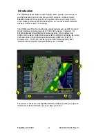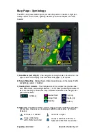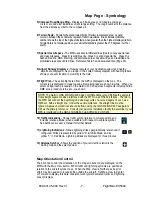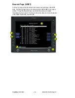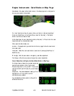
5) Compass Rose/Range Ring -
Displays a 360-degree or 120-degree compass
circle or arc and also indicates current range setting. The range number is the distance
from the airplane symbol to the compass arc.
6) Terrain Scale -
Shows highest and lowest limits of terrain in displayed area. Legend
colors in between these numerics represent terrain elevations. Blue obstacle clearance
number shows the top of the highest obstacle, when greater than the highest displayed terrain.
Terrain data is not displayed when your aircraft’s latitude is greater than 75 degrees (north or
south).
7) Special Use Airspace -
The MFD uses several different line styles to convey special use
and class airspaces. Class B is solid blue line, Class C is solid magenta line. Class D is
dashed blue line, MOA, Warning, and Alert areas are solid yellow lines, and restricted and
prohibited areas are solid red lines. Reference Table 5 and associated note (Page 35).
8) Airport Runway Diagrams -
Runway layouts of your destination airport and nearby
airports are displayed. As you range in, the scaled runway diagram with heading labels
shows your exact location in proximity to the field.
9) Flight Plan -
The active flight plan from the GPS is displayed on the map. The
current leg is displayed in magenta and all remaining legs are shown in white. When you
select an approach procedure on the Garmin 430, all approach segments including holds,
DME arcs, procedure turns, etc., are shown
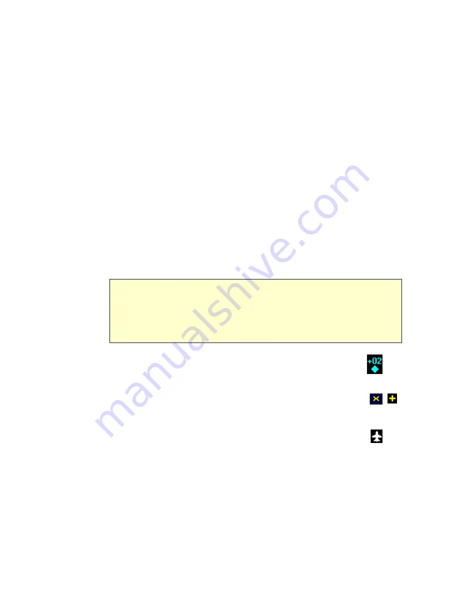
10) Traffic Indications -
Shows traffic symbol relative to current position and
includes relative altitude (when available) with respect to airplane symbol.
See traffic sensor user’s manual for further details.
11) Lightning Indications -
Shows lightning strikes geographically referenced if
configured. Strikes represented by yellow “X” in Strike Mode, and by
yellow “+” in Cell Mode. Lightning strikes are displayed for three minutes.
12) Airplane Symbol -
Shows the position of your aircraft in relation to the
moving map and the selected view.
600-00105-000 Rev 01
-7-
FlightMax EX5000
Map Page - Symbology
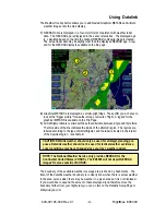
Map Orientation Control
The pilot can control the orientation of the map and sensor data displayed on the
MFD with the Map View button. MFD traffic and lightning symbols are positioned
relative to the aircraft symbol nose. When the Map View is North-Up extra pilot
effort may be needed to locate traffic outside the aircraft. Set Map View to Center
or Forward to display this data consistent with typical dedicated traffic and lightning
sensor displays.
NOTE: The Garmin GNS 430/GNC 420 does not differentiate curved flight path segments
from straight segments when interfaced with the MFD via an RS232 interface. Therefore,
the MFD will connect the beginning and end waypoints of a curved segment, such as a
DME arc, with a straight line. Under these circumstances, the straight line must be
ignored. Approach procedures should be flown using the GNS 430/GNC 420 navigator’s
CDI as the primary reference. Consult your avionics installation facility to determine if your
MFD is interfaced to the GNS 430/GNC420 via ARINC 429 or RS232.

