background image

FXT 5000 Series Field Service Guide

The software will show one or more dialog boxes that describe the impact of removing the node and ask you to con-
firm the removal by typing answers in a text box.

8.2.2 Adding the Node to the Cluster

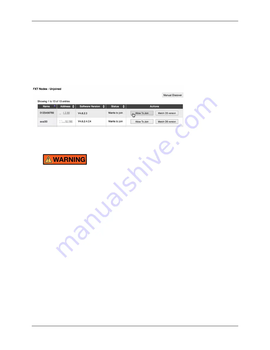
After powering on the replaced node, use a web browser to access the

FXT Nodes

page in the

Settings

tab of the

Avere Control Panel.

Find the replaced node in the

FXT Nodes - Unjoined

list and click its

Allow to Join

button.

8.3 Removing an FXT 5000 Series Node from a Rack

The inner rails on the FXT 5000 Series node chassis do not extend completely to the back of the chassis.
After disengaging the side locks, it is possible to completely pull the node out of the rack and off the
rails.

To avoid possible injury and equipment damage, always support the node completely after disengaging
the safety locks.

If completely removing the node from the rack, power it down and remove all cables and connectors. Also remove
the node from the cluster by using the Avere Control Panel as described in

Removing the Node from the Cluster Con-

figuration

(page 36).

8.3.1 Extending the FXT 5000 Series Node

To slide the node out to its extended position:

1. Loosen the captive screws at the front of each rail.

2. Slide the node forward until the latches on each side engage, stopping the chassis from moving forward.

8.3. Removing an FXT 5000 Series Node from a Rack

37

Содержание FXT 5000 Series

Страница 1: ...FXT 5000 Series Field Service Guide Avere Systems Inc 2018 04 05 www averesystems com Part number 0457 002 0171 rev B electronic version Part number 0457 002 0191 rev B printed version ...

Страница 2: ......

Страница 3: ...T 5000 Series Edge Filer Overview 9 3 1 Field Replaceable Units 9 3 2 Attaching a Console to an FXT 5000 Series Node 10 3 3 FXT 5000 Series Front and Rear Illustrations 10 3 3 1 FXT 5200 Front Illustration 10 3 3 2 FXT 5400 Front Illustration 11 3 3 3 FXT 5600 Front Illustration 11 3 3 4 Rear View of the FXT 5000 Series Models 11 3 4 Controls and LED Status Lights 12 3 4 1 Control Panel Buttons 12...

Страница 4: ...eries Differences from other Avere FXT Nodes 36 8 2 Removing the Node from the Cluster Configuration 36 8 2 1 Removing the Node from the Cluster 36 8 2 2 Adding the Node to the Cluster 37 8 3 Removing an FXT 5000 Series Node from a Rack 37 8 3 1 Extending the FXT 5000 Series Node 37 8 3 2 Removing the Node from the Rails 38 8 4 Installing an FXT 5000 Series Node in a Rack 38 8 4 1 Placing the Node...

Страница 5: ...ize yourself with the Avere FXT system by reading the following documents FXT 5000 Series Installation Guide https download averesystems com software FXT_5000_Installation_Guide pdf FXT Cluster Creation Guide http library averesystems com fxt_cluster Configuration Guide http library averesystems com operations The Avere OS Configuration Guide is written for system administrators who need to manage...

Страница 6: ...FXT 5000 Series Field Service Guide 2 Chapter 1 Introduction ...

Страница 7: ...ns of security and is con trolled by the authority responsible for the location Anyone entering the restricted access location or installing or replacing modules in an FXT Series node must be trained in the potential hazards associated with the FXT Series node including but not limited to exposure to hazardous energy levels when the cover is removed when modules have been removed or when modules a...

Страница 8: ...e earth grounding systems It has not been approved for use with IT type earth grounding systems Do not connect the node to any non TN type of earth grounding system To avoid the possibility of an electrical shock hazard the FXT Series edge filer must be properly connected to earth ground during the lifetime of the installation The edge filer receives its earth ground connection through the AC powe...

Страница 9: ...y and equipment damage observe the following precautions before installing nodes into racks or before removing them from racks Ensure that the node s weight is fully supported by two people at all times while it is being installed into or removed from a rack The rack installation must be designed to remain stable while supporting the full weight of the installed equip ment in its maximum extended ...

Страница 10: ...ce is provided in accordance with California Code of Regulations Title 22 Division 4 5 Chapter 33 Best Management Practices for Perchlorate Materials This product includes a lithium manganese dioxide battery that contains a perchlorate substance Perchlorate Material special handling may apply See www dtsc ca gov hazardouswaste perchlorate 2 6 3 Two Person Lift A bare node without accessories and o...

Страница 11: ...ly to the area immediately around the node For a node installed into an enclosed rack or a rack with perforated doors the ambient temperature requirement applies to the area inside the rack or door immediately around the node Operating the FXT Series node in a rack with open EIA U spaces can cause unintended airflow paths and as sociated temperature inconsistencies To maintain proper airflow and t...

Страница 12: ...strap Keep all electronic modules such as power supplies PCBs and disk drives in their original ESD protective packaging until you are ready to install them Handle all electronic modules carefully Do not touch connectors contacts or component leads Ensure that electronic modules do not come into contact with insulators such as clothing and plastics 8 Chapter 2 Precautions for Product Service and U...

Страница 13: ...oard Guide http library averesystems com operations Status LEDs are described in detail in the following sections of this document FXT 5000 Series Front and Rear Illustrations page 10 Control Panel Buttons page 12 FXT 5000 Series Front Panel LEDs page 13 FXT 5000 Series Rear Panel LEDs page 15 3 1 Field Replaceable Units Some devices can be replaced without opening the node The following is a list...

Страница 14: ...s configured as follows Speed 115200 baud Data bits 8 Stop bits 1 Parity None Flow control None To attach the console 1 Locate the serial COM1 port on the rear of the node 2 Use a null modem cable to connect the COM1 serial port to a terminal configured for ANSI 115200 8N1 3 Log in to the console 3 3 FXT 5000 Series Front and Rear Illustrations These diagrams show the front and rear layouts of FXT...

Страница 15: ...ervice Guide 3 3 2 FXT 5400 Front Illustration 3 3 3 FXT 5600 Front Illustration 3 3 4 Rear View of the FXT 5000 Series Models All FXT 5000 models have the same back layout 3 3 FXT 5000 Series Front and Rear Illustrations 11 ...

Страница 16: ...ster can properly recon figure itself when restarting In some circumstances the user might have no other choice but to use the power button to power off a node In that case follow this procedure 1 Press and release the power button once and wait The system will attempt to perform an orderly shutdown which can take several minutes If you do not see evidence of the node shutting down within five min...

Страница 17: ...wer failure Check that all power supplies are fully seated and that power cords are cor rectly installed Ensure that AC power is being applied to the power supply Reseat install cords and or apply power as required Check the power supply LEDs and the management interface for a failed power supply alert Use the information in the alert and the instructions in this guide to replace the failed power ...

Страница 18: ...ed from the remote web interface Avere Control Panel Turn off the LED by deactivating the remote UID in the IPMI web interface Front SAS Drive LEDs Each SAS drive has two status lights This chart applies to data drives and system drives LED name State Meaning Action if applicable Drive Ac tivity LED Unlit Drive is not installed or unit is not powered on Check for proper drive installation power on...

Страница 19: ... on N A Blink ing green Power is being supplied but the unit is powered off To power on the system press the power button on the front of the node Solid yel low This power supply is not receiving AC power but the other power supply is receiving power Check that the power supply is fully seated has a power cord installed and is connected to AC power Re seat each power supply install cords and or ap...

Страница 20: ...r Flashing green once per second 1Hz Driver loaded successfully Flashing orange once per second 1Hz Restore operation in progress Flashing red once per second 1Hz Backup operation in progress Flashing red twice per second 2Hz Reset operation in progress NVRAM Power LED Unlit Normal operation Flash green once Safe to remove Solid red DC DC power failure NVRAM Supercapacitor LED behind adapter panel...

Страница 21: ... to operate without interruption During a single power supply unit failure The node emits an audible alarm The information LED on the front of the node flashes red at 0 25Hz once every four seconds A yellow warning alert about a power supply error appears on the status page of the Avere Control Panel These conditions will continue until the failed power supply unit is replaced The information LED ...

Страница 22: ... lower right insert the replacement power supply unit into the node 6 Push the replacement power supply unit into the power bay until the red latch engages 7 Pull on the unit to ensure that it is properly seated in the node 8 Plug the power cord into the newly replaced power supply unit 9 Ensure that the information LED on the front of the node is no longer illuminated 10 Log in to the Avere Contr...

Страница 23: ...ears on the Avere Control Panel dashboard Click More details to show more information The informational message indicates that the drive is missing or has failed Click Node Settings to see the status of the FXT 5000 Series node that includes the drive Avere Control Panel loads the FXT Nodes page for the cluster Find the affected node in the list and click its name to show its Node Details page 19 ...

Страница 24: ... unused Refer to the diagrams in FXT 5000 Series Front and Rear Illustrations page 10 for more information If a data drive has failed follow the instructions in Replacing A Failed Data Drive page 20 If a system drive has failed follow the instructions in Replacing A Failed System Drive page 23 5 2 Replacing A Failed Data Drive As an overview there are three steps in replacing a failed data drive o...

Страница 25: ...ntil a replacement drive is received After replacing the drive you must reformat the node again to add the replacement drive to the node s data stor age system This process is not automatic Instructions are below in Reformatting the Node To Use the New Drive page 22 5 2 2 Data Drive Removal and Replacement Before replacing a failed data drive review the following warnings Hazardous Energy Levels p...

Страница 26: ... place by pressing the replacement drive assembly s lever until it locks into place Latching a drive in the chassis 4 Package the failed drive and return it to Avere Systems Instructions for returning the drive are included in the replacement part s shipping box or can be emailed from Avere Global Services After installing the replacement drive follow the steps in the next section Reformatting the...

Страница 27: ...the reboot the node will rejoin the cluster 5 3 Replacing A Failed System Drive The FXT 5000 Series nodes use mirrored system drives If a single system drive fails the other drive in the mirrored pair will keep the system operating When you receive a replacement system drive simply replace the failed drive to repair the node Avere OS will auto matically rebuild the mirror by copying the contents f...

Страница 28: ...own in the following illustrations press the maroon button on the drive assembly of the failed drive to release it A black lever is released from the front of the drive assembly Grasp the lever of the drive assembly and rotate it out to eject the drive Unlocking a drive 2 Remove the drive Use the lever to pull the drive assembly from the node chassis Note the number on the label applied to the ass...

Страница 29: ... or can be emailed from Avere Global Services 5 3 2 Replacing Both System Drives Follow these steps if you need to replace a pair of system drives on an FXT 5000 Series node that have both failed 1 Use the Avere Control Panel web interface to remove the node from the cluster A detailed description of this process is included in Removing the Node from the Cluster Configuration page 36 Open the FXT ...

Страница 30: ...see the relative position of the system drives Insert the replacement drive assembly into the slot of the drive being replaced then slide the assembly into the slot by pushing firmly on the bezel until the lever begins to close Completely seat each drive assembly by pressing the lever until it locks into place Latching a drive in the chassis 6 Power on the node by pressing the power button on the ...

Страница 31: ... Package the failed system drives and return them to Avere Systems Instructions for returning the drives are included in the replacement part shipping box or can be emailed from Avere Global Services 5 3 Replacing A Failed System Drive 27 ...

Страница 32: ...FXT 5000 Series Field Service Guide 28 Chapter 5 Replacing Failed Drives ...

Страница 33: ...er case It can be awkward to unlatch and remove the SFP modules or the fiber optic cables connected to them A flat head screwdriver might be needed to unlatch the SFP module Other convenient implements that are hard and relatively flat may be used a key pen cap or credit card might be useful Take care not to use excessive force on the modules or their latching handles 6 2 Removing an SFP Module To...

Страница 34: ...dule 6 3 Installing an SFP Module To replace an SFP module 1 Orient the replacement module so that the edge card connector is facing up 2 With the handle closed slide the module into the SFP port until it is firmly seated 30 Chapter 6 Replacing SFP Modules ...

Страница 35: ...llers Fans SAS midplane CPUs and heatsinks DRAM modules DIMMs PCIe drive controller adapters PCIe Ethernet networking adapters PCIe NVRAM adapters Front control panel Before opening a node to investigate any failure review the following warnings and notices Restricted Access page 3 Electrical Code Compliance page 4 Earth Grounding page 4 AC Mains Disconnect page 4 Racked FXT 5000 Series Nodes page...

Страница 36: ...y The steps in this chapter assume that you have received the typical Avere Systems replacement node kit which is shipped without data drives The data drive slots in the replacement node contain empty drive assemblies that must be replaced with the data drives from the failed node If your replacement node includes data drives skip the steps for removing and replacing the data drives 7 2 Removing a...

Страница 37: ...and any other connections from the node Note If your replacement node was shipped with data drives skip Step 5 5 Remove all six data drives from the node and set them aside These will be installed in the replacement node Refer to Data Drive Removal and Replacement page 21 for help unlatching and removing drives from the chassis 6 Remove the node from the rack as described in Racking and Unracking ...

Страница 38: ... to the failed node and then attach the power cords to the AC inputs on the new node s power supply units 6 Power on the FXT 5000 Series node by pressing the power button on the front of the node 7 Using the Avere Control Panel add the node back to the cluster as described in Adding the Node to the Clus ter page 37 Note The replacement node will have a node name that was randomly assigned before s...

Страница 39: ...trol Panel to add the node to the cluster Read Adding the Node to the Cluster page 37 to learn how 8 1 Precautions To avoid injury and equipment damage observe the electrical and other cautions listed in Precautions for Product Service and Use page 3 To avoid the potential for serious injury and equipment damage caused by rack tip over the equipment rack must be properly designed and installed The...

Страница 40: ...fely extract a node Several connectors and ports are different from previous systems and some are installed in a different orienta tion than they were in other Avere Systems products Even if you have previously worked with Avere FXT systems be sure to read the instructions here before attempting to install or service an FXT 5000 Series filer 8 2 Removing the Node from the Cluster Configuration Bef...

Страница 41: ...e back of the chassis After disengaging the side locks it is possible to completely pull the node out of the rack and off the rails To avoid possible injury and equipment damage always support the node completely after disengaging the safety locks If completely removing the node from the rack power it down and remove all cables and connectors Also remove the node from the cluster by using the Aver...

Страница 42: ...g an FXT 5000 Series Node in a Rack This procedure assumes that you are replacing an FXT 5000 Series node in a rack that already has the outer rails snapped in place in the rack Inner rails are pre installed on the sides of the replacement node s chassis For a new rack installation please follow the procedure in the FXT 5000 Series Installation Guide https download averesystems com software FXT_50...

Страница 43: ...orative face outward and the latch to the left 2 Hold the left side of the bezel away from the chassis and insert the two pins on the right side of the bezel into the holes located on the node s right side rack mount flange 3 Press the bezel s latch to the right to retract the two locking pins on the bezel s left side 4 Move the left side of the bezel into position so that the entire faceplate is ...

Страница 44: ...FXT 5000 Series Field Service Guide 40 Chapter 8 Racking and Unracking an FXT 5000 Series Node ...

Страница 45: ...tp www averesystems com support By phone US and Canada toll free 1 888 88 AVERE 888 882 8373 press 2 for support US 412 894 2570 press 2 for support United Kingdom 44 20 3695 1638 press 2 for support International 1 412 894 2570 press 2 for support By email to support averesystems com This information also is available from the Support tab in the Avere Control Panel web interface 41 ...

Страница 46: ...FXT 5000 Series Field Service Guide 42 Chapter 9 Contacting Avere Global Services ...

Страница 47: ...e United States and or other countries Apple Bonjour and Safari are trademarks of Apple Inc registered in the U S and other countries Google and Google Chrome are trademarks of Google Inc Intel is a trademark of Intel Corp in the U S and other countries Linux is the registered trademark of Linus Torvalds in the U S and other countries Microsoft Active Directory Windows Windows NT and Internet Expl...

Страница 48: ...r Creation Guide documents minor updates no version change 2017 03 02 updated images for SSD system drives rev B 2016 03 03 added FXT 5200 rev A 2016 01 20 initial release for FXT 5400 and FXT 5600 Part number 0457 002 0171 rev B electronic version Part number 0457 002 0191 rev B printed version 44 Chapter 10 Copyright and Trademark Information ...

Отзывы: