Troubleshooting
55
Avaya
t
RS9 UPS (9–18 kVA, 9-Slot Models) Site Preparation, Installation and Operator’s Manual
S
164201543 Rev A
S High AC Input
System
(A)
(B)
(C)
(Silence)
(Clear)
(ESC)
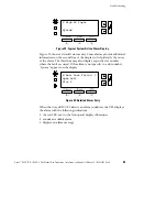
Figure 28. Typical System Active Alarm Display
Figure 29 shows a detailed alarm entry. Some alarms provide additional
information on the second line of the display to help identify the cause
of the alarm. The third line may also display a specific slot number
where the fault occurred. If the alarm is not specific to a slot number,
“System” appears on the display.
M Batt Test Failed
1
Open Cell
Slot 4
(A)
(B)
(C)
(Silence)
(Clear)
(ESC)
Figure 29. Detailed Alarm Entry
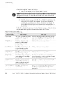
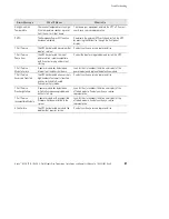
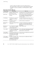
When the Avaya RS9 UPS detects an alarm condition, the UPS displays
the alarm with the following indications:
S
the red LED next to the front panel display illuminates
S
sounds an audible alarm
S
displays an alarm message

