LOAD DIAGRAM
The lifting capacity of the loader is limited by the possibility of tipping around the front axle. The diagram
below shows the tipping loads and max. allowed loads in different loading situations on an even level surface
with the loader in maximum articulation (i.e. minimum restoring moment).
200 Series
Load diagram
9
The diagram can be interpreted as follows:
The diagrams show max. loads with the boom in different positions and with the load at different distances
from the attachment coupling plate
Max. load should be reduced when the load is farther away from the attachment coupling plate
If the center of gravity of the load is 50 cm in front of the attachment coupling plate, max. load is 230 kg
with a driver weighing 80 kg and with a safety factor of 1,5 against tipping over (n=1,5)
With the load carried at low level max. load of 300 kg can be transported at the above mentioned case
Please note that the diagrams are based on the machine operating on a level, even and firm supporting
ground. Loads should be significantly reduced when operating on gradients and/or on soft ground.
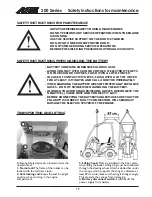
ALWAYS KEEP AND TRANSPORT THE LOAD AS CLOSE TO THE GROUND AS POSSIBLE
NEVER TAKE A HEAVY LOAD ON THE LOADER FROM HIGH LEVEL - E.G. FROM TRUCK,
SHELF ETC. - RISK OF TIPPING OVER!
ALWAYS PUT DOWN THE LOAD BEFORE LEAVING THE MACHINE
AVANT 200 series Load diagram
Max. load (n=1.5 80kg driver
Max. load (n=1.5 no driver)
0
0.50m 0.25m
1.00m
1.25m
0.75m
100kg
150kg
200kg
250kg
300kg
350kg
400kg
450kg
500kg


