


200 Series
How to work safely
5
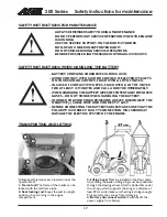
HOW TO WORK SAFELY
An incorrect or careless operation of the loader may
be the origin of a serious accident. Before putting the
machine into operation, familiarise yourself with the
use of the machine and read and understand this
Operators Manual as well as the safety instructions.
THIS SYMBOL INDICATES
THE IMPORTANT
SAFETY FACTORS.
Understand the limitations of speed, braking, steering
and stability as well as loading capacity of the machine
before starting operation. Make sure that every one
who operates or works with this equipment is familiar
with these safety precautions.
The loader must only be used for the tasks and with
the attachments approved by the manufacturer.
If you have no previous experience of the machine,
make sure to do all testing at a safe and open place
with no persons in the area of operation.
SAFETY INSTRUCTIONS
Never use the loader without instructions. Read loader
signs (decals), and this manual.
Start the operation slowly and carefully.
Do not wear loose clothing, long uncovered hair or
jewelry near machine.
When driving be comfortably seated in the driver´s
seat, keep your feet in their proper place in the footwell
and at least one hand on the steering wheel.
Operate the control levers and the lever of auxiliary
hydraulics only when sitting in the driver´s seat.
Operate the control levers with ease and without
hesitation.
When coupling the attachment, make sure that the
locking pin locks in positively.
Never put any part of the body or let anyone go under
the lifted boom.
Do not transport persons in the bucket. The machine
is not designed to lift or to transport persons.
Keep hands, feet and clothing away from any moving
part and/or hydraulic cylinder.
Never carry passengers. Keep other bystanders away
from the work area.
Drive slowly on uneven terrains. Watch out for ditches,
manholes and steep gradients.
Do not drive on too steep a gradient. Load, unload, and
turn on flat level ground.
Make sure that the ventilation is sufficient when working
indoors or otherwise confined area.
Do not use loader in an atmosphere with explosive dust
or gases or where exhaust can contact flammable
material, explosion or fire can result.
Do not transport the load with the boom lifted.
Always carry bucket or attachment as low as possible,
and put the load down whenever you leave the machine.
When lifting or lowering the load, do not operate the
boom control lever abruptly. Turn the lever smoothly
and with care.
Do not exceed rated operating capacity - follow the
load diagrams.
Do not park the machine on a surface with a gradient.
Should this be necessary, use the parking brake and
preferably turn the machine sideways and put down
the bucket. If needed, use chocks behind the wheels.
Before leaving driver´s seat:
- Lower the loader boom
- Place attachment flat on ground
- Stop the engine, remove the key
- Engage the parking brake
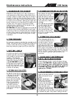
Never perform any maintenance or repair operation
when the engine is running.
Stop and cool the engine before adding fuel.
Keep the engine area clean of flammable materials.
Wear eye protection when servicing, and hard hat or
other protective equipment as needed.
When connecting a booster battery for "jump" start,
always make last connection (negative cable) to engine,
never at battery. When removing the "jump" start cable,
always remove the negative cable (-) from engine first.
Never charge a frozen battery.
Lead acid batteries produce flammable and explosive
gases. Keep arcs, sparks, flames and lighted tobacco
away from battery.
Battery acid causes severe burns. In case of acid contact,
wash immediately with water for several minutes and
get medical attention in case of eye contact.
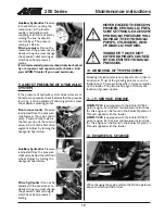
Use a piece of cardboard to check for hydraulic leaks.
Leaking fluids under pressure can enter the skin and
cause serious injury. Medical attention is required if
hydraulic or other fluids contact skin.
Never modify the loader or add attachments not
approved by
AVA
NT
Tecno Oy.
Do not smoke during refueling or driving.
If the loader is transported e.g. on a trailer, make sure
that the articulation joint is securely locked by fitting
the frame lock (painted red, see p. 17) on the left side.
Ensure it is removed before commencing driving again.
When turning with the loader, keep in mind that the
chassis extends beyond the turning radius of the
wheels (collision risk).
Read this Operator's Manual carefully, especially if you
are unfamiliar with the safe use and operation of the
machine.


