background image

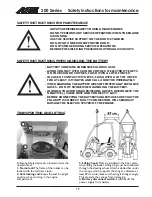
Steering of the machine

14

NOTICE! THE ENGINE CANNOT

START IF THE AUXILIARY

HYDRAULICS CONTROL PEDAL IS

IN THE LOCKING POSITION.

THE OPERATING DIRECTION OF

THE ATTACHMENT DEPENDS ON

THE COUPLING OF THE

ATTACHMENT HOSES. MAKE SURE

THAT THERE ARE NO PERSONS IN

THE DANGER AREA WHEN

TESTING THE OPERATING

DIRECTIONS. CHANGE THE

COUPLING OF THE HOSES IF

NECESSARY.

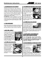
STEERING OF THE MACHINE

Steering of the machine is actuated via the steering

wheel. The steering wheel is hydraulically powered.

A practical way of steering is to steer with your left

hand on the knob of the steering wheel. This way

your right hand is free to operate other functions.

Familiarise yourself with the special drive features and

space needs of this articulated loader on a flat, even

and open place. Remember that, when turning, the

front frame of the loader extends beyond the turning

radius of the wheels.

LOADER CONTROL

The loader boom and bucket are controlled with the

multi-function lever sideways (tilt) and back & forward

(boom up & down).

· Pull backward to lift the boom

· Push forward to lower the boom

· Push left to raise the tip of the bucket (filling)

· Push right to lower the tip of the bucket (emptying)

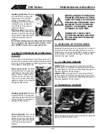
USING THE AUXILIARY HYDRAULICS

Auxiliary hydraulics (hydraulically operated attachments)

are controlled with the pedal no. 14 in the footwell.

Auxiliary hydraulics control pedal locks in the locking

position (down left) which facilitates operation of the

attachments that require constant oil flow (rotary

broom, backhoe etc.).

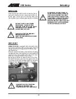
HAND THROTTLE

When driving, the

revolution speed of the

engine can be adjusted

with the hand throttle

lever, if necessary. Do

not turn the machine

with a high driving travel

speed.

NEVER TIP OVER THE LOADER.

NEVER USE A HIGH DRIVE SPEED

WHEN TURNING.

In particular: when the loader boom is up

the stability of the machine is much weaker

when turning.

WHEN DRIVING, ALWAYS KEEP

THE LOADER BOOM AS LOW AS

POSSIBLE. 

Risk of tipping over increases

considerably when there is a heavy load

on the loader (a heavy attachment or a

big load in the bucket) and the boom is

up when driving.

ALWAYS REMEMBER – SAFETY

FIRST.
TEST ALL THE FUNCTIONS OF THE

LOADER AT AN OPEN AND SAFE

PLACE.
MAKE SURE THAT THERE ARE NO

PERSONS IN THE OPERATING

AREA OF THE MACHINE.

200 Series

Содержание 218

Страница 1: ...Operator s Manual 2013 English ...

Страница 2: ...VE CONTROL 13 FUNCTION OF DRIVE PEDALS 13 STEERING OF THE MACHINE 14 LOADER CONTROL 14 USING THE AUXILIARY HYDRAULICS 14 HAND THROTTLE 14 COUPLING THE ATTACHMENTS 15 MAINTENANCE SCHEDULE 16 MOUNTING OF THE SERVICE SUPPORT 16 SAFETY INSTRUCTIONS FOR MAINTENANCE 17 SAFETY INSTRUCTIONS WHEN HANDLING THE BATTERY 17 TRANSPORTING AND LIFTING 17 MAINTENANCE INSTRUCTIONS 18 FILTER LOCATION 20 GREASING POI...

Страница 3: ...losses resulting from any failure of the product 4 Only AVANT Tecno Oy approved replacement or original quality parts shall be used during routine maintenance 5 Any damage caused by the use of incorrect fuel lubricants cooling liquid or cleaning solvents is excluded 6 The Avant Warranty excludes any consumable parts e g tyres spark plugs batteries filters belts etc except where it can be clearly s...

Страница 4: ...y 2004 108 EEC EMC and 2000 14 EC Noise Emission 5 Category EARTH MOVING MACHINERY LOADERS COMPACT 6 Model AVANT 7 Serial Number 8 Year of Manufacture 9 Directive Conformity Assessment Procedure Notified Body 2006 42 EC Self certification 2004 108 EEC Self certification 2000 14 EC Type test MTT Agricultural Engineering Research VAKOLA Vakolantie 55 03400 Vihti FINLAND 10 Name Risto Käkelä 11 Posit...

Страница 5: ...s or where exhaust can contact flammable material explosion or fire can result Do not transport the load with the boom lifted Always carry bucket or attachment as low as possible and put the load down whenever you leave the machine When lifting or lowering the load do not operate the boom control lever abruptly Turn the lever smoothly and with care Do not exceed rated operating capacity follow the...

Страница 6: ...Decal locations 6 200 Series l j k m n o DECAL LOCATIONS If any of these decals has been removed or is unreadable it should be replaced without delay l j k m n o ...

Страница 7: ...ts the front and back frame The loader is steered hydraulically by the steering cylinder which is mounted between the front and back frames Loader boom Loader boom is mounted on the front frame with two pivot pins The attachment coupling plate is mounted on the lower end of the boom Loader boom is equipped with a self leveling system It keeps the bottom of the attachment e g bucket pallet fork lev...

Страница 8: ...r AVANT 220 29 l min 185 bar 1 8 2 4 850 2100 mm 1470 mm 600 daN 350 kg Model Engine type Function Cooling system Number of cylinders Starter Bore stroke Displacement Max output Fuel Fuel tank capacity Engine oil capacity Engine oil type Viscosity Valve clearance suction Valve clearance exhaust Sound pressure level LPA Sound output level LWA AVANT 218 Kohler CV620 4 stroke air 2 electric 77 67 mm ...

Страница 9: ... 50 cm in front of the attachment coupling plate max load is 230 kg with a driver weighing 80 kg and with a safety factor of 1 5 against tipping over n 1 5 With the load carried at low level max load of 300 kg can be transported at the above mentioned case Please note that the diagrams are based on the machine operating on a level even and firm supporting ground Loads should be significantly reduc...

Страница 10: ...9 10 11 13 14 15 16 1 Steering wheel 2 Hour meter 3 Ignition switch 4 Signal horn 5 Light switch 6 Fuse box 7 Control lever of boom and bucket 8 12 V outlet 9 Hand throttle lever 10 Choke 11 Drive pedal right drive forward 12 Drive pedal left drive backward 13 Parking brake handle 14 Lockable auxiliary hydraulics control pedal 15 Oil temperature gauge optional extra 16 Drive circuit release valve ...

Страница 11: ...drive forward 12 Drive pedal left drive backward 13 Parking brake handle locking turn left and down into locking position releasing turn right and up to release parking brake if necessary make a sharp turn with the steering wheel so that the locking pins unlock in the front wheels 14 Control pedal of auxiliary hydraulics hydraulically operated attachments Lift the pedal carefully to test the opera...

Страница 12: ...push choke button down as soon as engine has started push completely down when engine has warmed up Turn the ignition key to the OFF position to the left Turn the power off with the battery disconnect switch STOPPING THE ENGINE THE ENGINE CANNOT START IF THE AUXILIARY HYDRAULICS CONTROL PEDAL IS IN LOCKING POSITION LOCATION OF BATTERY DISCONNECT SWITCH All AVANT loaders are equipped with a battery...

Страница 13: ...ct in a proportional way to control the drive speed and power available at the drive motors This hydrostatic drive system has different operating characteristics to a mechanical drive To get maximum pushing power push the pedals lightly for higher travel speed push the pedal harder Driving of the machine is controlled with the drive pedals as follows Select the revs of the engine with the hand thr...

Страница 14: ...ard to lift the boom Push forward to lower the boom Push left to raise the tip of the bucket filling Push right to lower the tip of the bucket emptying USING THE AUXILIARY HYDRAULICS Auxiliary hydraulics hydraulically operated attachments are controlled with the pedal no 14 in the footwell Auxiliary hydraulics control pedal locks in the locking position down left which facilitates operation of the...

Страница 15: ...t so that the lower edge of the attachment coupling plate turns into the attachment Stage 4 Pull the boom control lever more to the left so that attachment coupling plate turns more and the boom pushes the pin down in the hole of the attachment CAUTION Make sure that the pin locks properly down in the hole of the attachment Stage 5 If the attachment is equipped with hydraulic hoses make sure to co...

Страница 16: ...iment cup 15 Clean spark arrester 16 Change spark plug 17 Change engine oil filter 18 Change air cleaner element 19 Check and adjust valve clearances Every week Every year Every 1000 h Every 800 h Every 500 h Every 400 h Every 200 h Every 100 h After 50 h After 25 h Every day l l l l l l l l l l l l l l l l l l n n n n n n l Maintenance operation n When necessary More specific engine maintenance i...

Страница 17: ... DO NOT SMOKE WHEN HANDLING THE BATTERY IN ORDER TO AVOID SPARK EMISSIONS ALWAYS DISCONNECT THE NEGATIVE CABLE FIRST AND CONNECT IT LAST BEFORE CONNECTING THE BATTERY CABLES MAKE SURE THAT THE POLARITY IS CORRECT FAULTY CONNECTION WILL SERIOUSLY DAMAGE THE ELECTRIC SYSTEM OF THE ENGINE TRANSPORTING AND LIFTING Following safety devices are located under the operator seat 1 Frame lock The frame of t...

Страница 18: ... the two marks in the dipstick Refill when necessary Clean the area before checking hydraulic oil level Do not let any contaminents enter the hydraulic tank during this procedure 5 CHANGING OF HYDRAULIC OIL FILTERS The hydraulic oil return filter is located on top of the hydraulic oil tank under the right cover beside steering wheel Take off the cover and replace the oil filter cartridge The hydra...

Страница 19: ...alve behind the left front wheel Adjust by turning the hexagonal head screw Drive hydraulics Can not be adjusted If the pressures are clearly wrong one must change the pressure relief cartridges which have fixed pressure setting 10 GREASING OF THE MACHINE Greasing of pivot points is very important in order to avoid wear Most of the greasing points are on the loader boom There are altogether 10 gre...

Страница 20: ...nder both ends 5 Shot bolts and joint in attachment coupling plate 6 Articulation joint 7 Steering cylinder 1 Hydraulic oil filter pressure 2 Fuel filter 3 Air filter element 4 Air filter outer 5 Hydraulic oil filter return 6 Engine oil filter A46683 218 220 Filter kit AVANT 218 220 64825 Air filter element 64826 Air filter outer 74093 Hydr oil filter return 64807 Hydraulic oil filter pressure 648...

Страница 21: ... over a long period of time and may need tightening There is a hole in the bottom of the loader for checking the tightness of the drive belt Belt is correctly tightened when it moves in the middle of the belt 9 mm when 70 N force is applied look at the picture Belt tightening device increases tension of the drive belt pulls the pump away from the engine when the two screws on the right are being t...

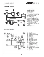
Страница 22: ...mp 2 adjustment pressure relief valve M Control valve for the hydraulic outlet of the accessories N Quick couplings of the hydraulic outlet O Oil cooler P Drive release valve ELECTRICAL HARNESS e1 Earth cable 19 Elecrical main switch e2 Grounding cable from battery e3 Battery 12 V e4 Starter motor e5 Regulator e6 Fuel stop valve e7 Oil cooler fan e8 Reverse beeper optional e9 Reverse switch option...

Страница 23: ...____________________ 2 _________ __________ ________________________________________________________________ 3 _________ __________ ________________________________________________________________ 4 _________ __________ ________________________________________________________________ 5 _________ __________ ________________________________________________________________ Remedy Make sure that the h...

Страница 24: ... 2013 AVANT Tecno Oy All rights reserved Printed in Finland 1013 ...

Отзывы: