background image

P. 6


Installation 

Guide

 AS-1585 SH

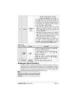
This wire will allow the Remote Car Starter to 
sense whether the Engine is running. The wire 
requires at least 1.8 V (AC) and 1.6 Hz or faster 
when the Engine runs at idle speed. Among 
common references for the Tach wire are: the 
negative side of the Ignition Coil, the Camshaft 
sensor, the Crankshaft sensor or the Engine 
Control Module (ECM). 

2

PURPLE

(A.C.)

Tachometer 

input 

Note:

 if the Tach signal is too low, the Remote 

Car Starter will “over-crank”. Conversely, if the 
Tach signal is too high, the Remote Car Starter 
will “under-crank”. 

3

GREY

(–) Hood Switch 

input 

Connect this wire to the installed Hood Pin switch 
supplied. This input will disable or shut down the 
Remote Starter when the Hood is up. 

4

ORANGE

(+) Brake Switch 

input 

This wire must be connected to the Brake Light 
wire of the vehicle. This wire must have +12 V 
only when the Brake Pedal is down. This input 
will shut down the Remote Starter if the Brake 
Pedal is pressed. 
This wire provides a +12 V output and must be 
connected on the vehicle to the Parking Lights 
wire that tests +12 V when the Light switch is in 
the

ON

 position.

5

YELLOW

(+) 12 V Parking 

Light output 

Note

: ensure that the voltage does not decrease 

or increase when the dimmer control switch is 
turned. If the voltage goes up or down, find 
another Parking Light wire. 


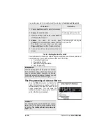
12-Pin Accessories Harness 

Wire

Colour 

Function 

Description 

1

BLUE

(–) Trunk / 

AUX 3 

output 

500 mA negative output. This output can be used to 
control the Trunk release (1-sec. pulse), or it can be 
set to operate as a constant output as long as the 

TRUNK

 button is held pressed (for Sunroof or 

Window closure) 

2

BROWN

(–) Lock output 

Programmable 500 mA negative output: 1/10-sec., 
7/10-sec. or 4-sec. pulse

3

GREEN

(–) Unlock output

Programmable 500 mA negative output: 1/10-sec., 
7/10-sec., 4-sec. or double 1/4-sec. pulse (

ON

250 ms, 

OFF

 500 ms, 

ON

 250 ms). 

Содержание AS-1585 SH

Страница 1: ...lease note that this guide has been written for properly trained Autostart technicians a certain level of skills and knowledge is therefore assumed Please review the Installation Guide carefully befor...

Страница 2: ...ight Flash Table 25 Introduction This Guide contains all the information relevant and necessary for the installation of the Remote Car Starter Most of the features of this product are explained in the...

Страница 3: ...leave a window open Never leave the keys in the car Leave them on a workbench with a window rolled down If possible remove courtesy light fuse to prevent battery drain The PROGRAMMING ASSISTANCE BUTTO...

Страница 4: ...nections Should the Unit be powered up before being grounded there could be serious damage to internal components of the Unit Be careful not to power up a Remote Car Starter before it is properly grou...

Страница 5: ...h of certain vehicles there may be more than one Ignition wire for powering the Heater Blower Motor Use the 5th relay Pin F and extra relays to power up any extra Ignition wires if necessary Do not ju...

Страница 6: ...This wire must have 12 V only when the Brake Pedal is down This input will shut down the Remote Starter if the Brake Pedal is pressed This wire provides a 12 V output and must be connected on the vehi...

Страница 7: ...ltaneously It is essential that the Remote Car Starter be connected in such a way as will allow each one of the Doors to turn off Ready Mode the driver side Door Pin does not constitute by itself a su...

Страница 8: ...s enabled UNLOCK pulse s will be sent with DISARM a LOCK pulse and a REARM pulse will be sent when the Trunk is closed or if the Trunk was left closed Option 2 Default Engine Start Stop The first Grou...

Страница 9: ...s essential that the Remote Car Starter be connected in such a way as will allow each one of the Doors to turn off Ready Mode the driver side Door Pin does not constitute by itself a sufficient connec...

Страница 10: ...The Remote Car Starter will only accept positive Glow plug input signals therefore negative Glow Plugs should only be connected using relays to invert the polarity A diode must be added between the n...

Страница 11: ...the very last steps in the installation process 2 Pin Harness Wire Colour Function Description 1 BLUE WHITE AUX 2 output This 500 mA negative output can be programmed for one of the following Options...

Страница 12: ...fferent sub menus which will be described later in this Guide a Transmitter Programming b Programming Options c Honk Horn Timing if available d Tach Programming Remember Once the Parking Lights are ON...

Страница 13: ...es quickly The Remote Car Starter has stored the code of the Transmitter into memory 3 To exit close the Hood Table 2 Programming a Transmitter To program a Transmitter on the second vehicle for Multi...

Страница 14: ...e selected Option Please note that the different Functions within any particular Mode can only be accessed sequentially the Programming Centre will move from Function 1 to Function 2 then to Function...

Страница 15: ...h 4 minute Run Time in Cold Weather Mode OPTION 3 Diesel Mode with 9 minute Run Time in Cold Weather Mode FUNCTION 5 Ignition Valet OPTION 1 Ignition Valet DISABLED OPTION 2 Ignition Valet ENABLED OPT...

Страница 16: ...e Tach signals of certain Ignition systems are sometimes too low or too high for the Remote Car Starter causing failed start ups at various temperatures 1 Flash the Hood Pin switch see Table 1 The Par...

Страница 17: ...the pulse by 10 ms press the TRUNK button 5 To save the new settings press LOCK and UNLOCK If 3 honks are returned the new settings have been saved Table 9 Adjusting Honk Duration Otherwise close the...

Страница 18: ...Brake shutdown circuit With the vehicle running under the Remote Car Starter press and release the Brake Pedal The Engine should shut down immediately If the Engine continues to run check the Brake Sw...

Страница 19: ...ers of this series are equipped with an on board high current programmable 5th Relay that can be used to power a second Ignition Accessory or Crank wire The Unit uses 3 sets of pins each set correspon...

Страница 20: ...lutch switch to the starter motor When the key is turned to the START position without pressing the pedal you will test 12 V only on one of the wires at the clutch switch this is the key side When the...

Страница 21: ...wo examples the clutch was bypassed by engaging the clutch relay In an N C system a relay is also used to interrupt the starter wire In order to bypass an N C Clutch one must prevent the Clutch relay...

Страница 22: ...ill start the Engine and arm the Starter Kill but the Doors will not be locked or unlocked at any moment of the sequence Lock Pulse Duration The duration of the Lock and Unlock pulses can be configure...

Страница 23: ...ntering Programming Mode 3 The Parking Lights will flash 8 times to confirm resetting Table 10 Resetting without a Valet Button On some vehicles such as BMW and certain Volkswagen vehicles resetting w...

Страница 24: ...the most recent event first then the second one and so on If there is no event at all to report the Parking Lights will give one long flash Start Failure Codes through the Parking Lights 1 x No Start...

Страница 25: ...Valet Mode 2 pause 2 x There was an attempt to start the vehicle while the Remote Car Starter was in Home Valet Mode 4 pause 3 x The vehicle went out of Ready Mode 12 V detected on the Brake Line 10 p...

Отзывы: