AutoPatch 8Y-3000 Скачать руководство пользователя страница 48

6. Review the Readme.txt file found on either Disk 1 or after

installation in the default install location C:\AutoPtch\Connect\.

To launch X

N

Connect:

1. From the Start menu, select Programs.

2. Select AutoPatch Applications (or any other file group you selected

during the install).

3. Select the Connect file group.

4. Select the Connect program.
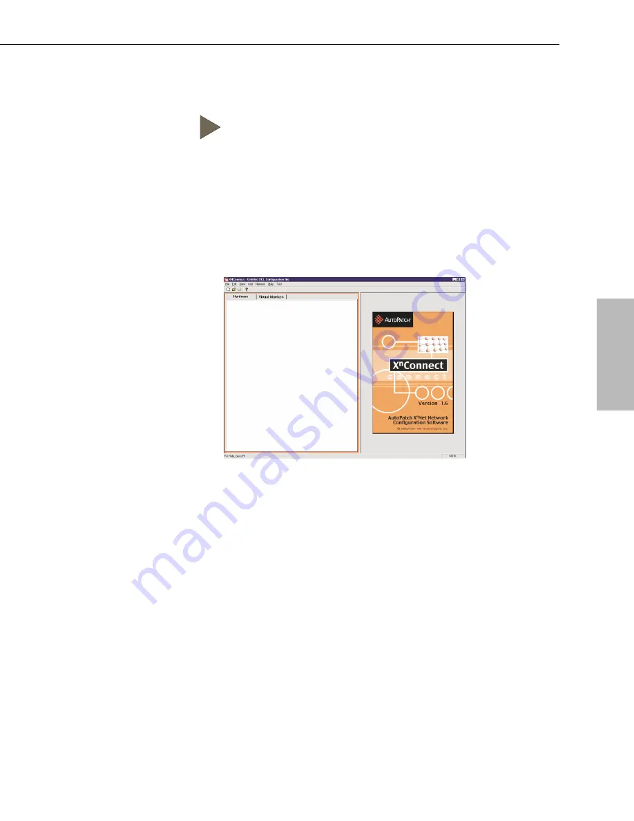
The X

N

Connect program opens.

8.3 Panes, Views, and Dialog Boxes

X

N

Connect displays two panes. The graphics are located in the left pane

and the properties of the currently selected graphic are in the right pane.
At the top of the left pane, you can access the different graphical
representation views from two tabs: Hardware and Virtual Matrices.
Hardware, such as enclosures and control panels, appear in the Hardware
view and existing virtual matrices appear in the Virtual Matrices view.
As you switch from view to view, the properties displayed in the right
pane automatically change to correspond to the new graphics.

Installation and Setup Guide

8-3

Panes, Views, and Dialog Boxes

Configuration

Files

Содержание 8Y-3000

Страница 1: ...8Y 3000 Documentation Set q 8Y 3000 New Features q 8Y 3000 Installation and Setup Guide q 8Y 3000 User s Operation Manual...

Страница 2: ...rollable via Ethernet Neuron RS 232 RS 422 and a variety of XN Net based control panels 10 Base 2 Ethernet interface Neuron Control network 76 Kbps free topology Software selectable RS 232 or RS 422 S...

Страница 3: ...8Y XL Installation and Setup Guide Version A0 Version B0 905197...

Страница 4: ...igned for this purpose Anyone performing field maintenance on AutoPatch equipment should utilize an appropriate ESD field service kit complete with at least a dissipative work mat with a ground cord a...

Страница 5: ...ng or removing boards unless otherwise specified in that product s documentation To avoid shock or potential ESD Electrostatic Discharge damage to equipment make sure you are properly grounded before...

Страница 6: ...ation du appareil Pour viter les chocs ou les dommages ventuels caus s l quipement par une d charge lectrostatique veillez ce le dispositif oit bien reli la terre avant de toucher les composantes se t...

Страница 7: ...e without notice The United States Federal Communications Commission in 47CFR 15 838 has specified that the following notice be brought to the attention of the users of this product Federal Communicat...

Страница 8: ...U S Government Printing Office Washington D C 20402 Stock N 004 000 00345 4 8Y XL XN Net and XN Connect are trademarks of XN Technologies Inc Use shielded cables To comply with FCC Class B requirement...

Страница 9: ...Patch products shipped on or after October 1 1997 The Limited Lifetime warranty applies to products in the original installation only If the product is moved to a different installation the Limited Li...

Страница 10: ...e use of or inability to use AutoPatch products 7 AutoPatch will not be responsible for items damaged during shipment to or from AutoPatch The shipping carrier is responsible for items damaged during...

Страница 11: ...Enclosures Chapter 4 Attaching Inputs and Outputs Attaching Input and Output Cables 4 2 Paralleling Inputs 4 4 Chapter 5 Attaching an External Controller Chapter 6 Applying Power and the Startup Seque...

Страница 12: ...nd Output Boards 10 2 Vertical Interval Timing Board 10 3 Adding Enclosures 10 5 Appendix A AutoPatch Service and Returns Policy Service A 1 Return Authorizations A 1 Claims for Shipping Damages A 1 R...

Страница 13: ...e a companion to the User s Operation Manual The 8Y XL Installation and Setup Guide is designed to provide the installation technician with quick easy to follow instructions for installing an 8Y XL an...

Страница 14: ...from a variety of sources including a CP 10 Control Panel a CP 10 Remote Control Panel any control device that can send ASCII characters through an RS232 or RS422 serial cable a third party serial co...

Страница 15: ...P 10 Control Panel Startup sequence from a serial control device Chapter 7 Executing a Test Switch Directions for executing a test switch from the CP 10 Control Panel Directions for executing and disc...

Страница 16: ...ch enclosure and is designed for system control of the 8Y XL Distribution Matrix ESD Electrostatic Discharge ESD refers to electrical charges such as static electricity that can damage sensitive compo...

Страница 17: ...onfiguration information see the XN Connect Help file for assistance XN Net XN Net is an internal communication protocol that requires software driver support for Ethernet and Neuron interfaces Techni...

Страница 18: ...he first blank is the box number and the second blank is the total number of boxes in the shipment Box 1 contains several additional items q Packing list q Installation and Setup Guide q User s Operat...

Страница 19: ...ping boxes at cost 1 1 Front of the Enclosure Enclosures are the structural basis of an 8Y XL Distribution Matrix Since AutoPatch matrix switchers are custom built for each installation factors such a...

Страница 20: ...d Preset values use the number keys Number Keys 0 9 Use the number keys to enter digits when choosing front panel menu items instead of scrolling down the lists entering input output and local preset...

Страница 21: ...ery the system for signal routing information and switch verification Level Key The Level key prepares the system to receive a level identification number as the next entry Change Key Use the Change k...

Страница 22: ...sing the key again Space Key Use the Space key to insert a space between multiple outputs or multiple local presets when entering a command the output and local preset prompts are the only prompts tha...

Страница 23: ...of the CPU A single enclosure can handle a combination of analog audio analog video digital video and sync signals 1 6 Installation and Setup Guide Unpacking the 8Y XL 57 58 59 60 61 62 63 64 13 14 15...

Страница 24: ...left corner of the rear of the enclosure The power supply holds the power switch power connector and fuse drawer The power supply fan vent is to the right of the power supply unit The 8Y XL input volt...

Страница 25: ...tween them Caution Avoid placing high heat producing equipment directly above or below the enclosure s 8Y XL enclosures are designed to adequately dissipate the small amount of heat they produce under...

Страница 26: ...wer to each enclosure and turn on the entire system See Chapter 6 Applying Power and the Startup Sequence WE RECOMMEND SURGE PROTECTORS AND OR AN AC LINE CONDITIONER 5 Perform a test switch to ensure...

Страница 27: ...m XN Net 16 gauge twisted pair 492 ft 150 m In a multi enclosure system with an external controller the enclosure connected to the control device receives all control information and passes on relevan...

Страница 28: ...shown in the graphic below 3 2 Installation and Setup Guide Linking Enclosures 57 58 59 60 61 62 63 64 13 14 15 16 33 34 35 36 37 39 38 40 42 41 43 44 21 22 23 24 17 18 19 20 5 6 7 8 9 10 12 11 1 2 3...

Страница 29: ...in the same way as in step one Installation and Setup Guide 3 3 57 58 59 60 61 62 63 64 13 14 15 16 33 34 35 36 37 39 38 40 42 41 43 44 21 22 23 24 17 18 19 20 5 6 7 8 9 10 12 11 1 2 3 4 29 30 31 32 2...

Страница 30: ...e numbered separately The numbering starts at the top left and goes across two connectors This pattern repeats downward to the bottom of the section and then continues from the top on the remaining tw...

Страница 31: ...Patch 8Y XL Connector and Groupings Guide and then perform a test switch to verify that the system is working properly See Chapter 7 for details on performing a test switch To attach video inputs and...

Страница 32: ...connections and the graphic on the next page shows unbalanced audio connections Note For audio signals using twisted pair wire connect the shield only at one end to minimize low frequency noise Instal...

Страница 33: ...ion and Setup Guide Attaching Inputs and Outputs Inputs and Outputs GND 33 34 35 36 37 39 38 40 INPUT GND 33 34 35 36 37 39 38 40 OUTPUT Unbalanced audio connections Signal Direction Signal Direction...

Страница 34: ...4 35 36 37 39 38 40 42 41 43 44 21 22 23 24 17 18 19 20 5 6 7 8 9 10 12 11 1 2 3 4 29 30 31 32 25 26 27 28 46 48 45 47 57 58 59 60 61 62 63 64 51 49 50 52 56 55 53 54 13 14 15 16 21 22 23 24 17 18 19...

Страница 35: ...l of the boards among which the signal is split must be high impedance For example in the system pictured on the previous page the I O board in the top enclosure should be 75W and the board in the bot...

Страница 36: ...XN Net all ports including serial Control systems and panels such as SBCs and remote control panels usually connect to the XN Net connector Third party controllers and PCs usually connect to the seria...

Страница 37: ...in mappings The pin diagram above allows for hardware flow control If this type of control is not needed connect pin 7 to pin 8 on the PC s connector 5 2 Installation and Setup Guide Attaching an Exte...

Страница 38: ...mended settings also default settings for serial communication with an 8Y XL are BAUD 9600 Data Bits 8 Stop Bit 1 Parity NONE Note Make sure the settings on both the PC serial communication software a...

Страница 39: ...arth grounded power cord system with this matrix switcher The system s universal power supplies will accept all major international standard power sources see page B 1 for power supply specifications...

Страница 40: ...1 side of the power switch to turn it on 6 2 Startup from the CP 10 Control Panel After applying power and turning on the enclosure s the CP 10 Control Panel displays the Command screen The system is...

Страница 41: ...version 0 1 5 D Built on May 07 2001 15 17 57 System PLD version A6 System startups 20 cumulative service hours 257 0 total switches 1581 XNet address 0x04ab NVRAM settings warm reboot User preference...

Страница 42: ...ands Note Before executing a test switch attach only the first two inputs and outputs described in the AutoPatch 8Y XL Connector and Groupings Guide that came with your system The CP 10 test switch ex...

Страница 43: ...onnected exactly as shown on the AutoPatch 8Y XL Connector and Groupings Guide To execute a test switch using the CP 10 Control Panel 1 At the Command screen press the Change key The Change screen app...

Страница 44: ...to make sure the source and destination devices are turned on q Check all link and signal connections on the rear of the enclosure s to make sure everything is physically set up correctly q Attempt t...

Страница 45: ...minal program attached to the matrix CL0I1O2T For a complete list of BCS commands see Appendix C in the back of this guide If the switch did not execute properly q Check all power switches to make sur...

Страница 46: ...e cover of the User s Operation Manual Installing the AutoPatch Configuration Software set uploads XN Connect a graphical software program that can be used to modify and download configuration informa...

Страница 47: ...ormation can then be downloaded to the system s CPU s 8 2 Installing and Launching XN Connect is a graphical software program that displays your most recent configuration and allows easy addition of l...

Страница 48: ...s two panes The graphics are located in the left pane and the properties of the currently selected graphic are in the right pane At the top of the left pane you can access the different graphical repr...

Страница 49: ...the new configuration information to your system To open a configuration file in XN Connect 1 From the Getting Started dialog box click Open Configuration File 2 Using the standard File Open dialog b...

Страница 50: ...nals such as R G B H and V are grouped into a single channel to permit the simultaneous switching of them as an aggregate signal RGBHV Each component signal must have all sources and destinations with...

Страница 51: ...limited to eight characters for the new preset This step is required in order to create a new preset 4 Enter a description This step is optional 5 Click OK to add the newly named preset to the Existin...

Страница 52: ...ource button All instances of the selected source will be cleared from the Assignment column of the Destination Channels list Clear Destination by selecting a destination channel s multiple select by...

Страница 53: ...ntil the modified configuration file is downloaded see Section 8 4 to the system Modifying Groupings The process for modifying groupings takes you through two dialog boxes that allow you to assign con...

Страница 54: ...age Virtual Matrix Groupings dialog box will reappear with the results displayed in the read only box at the bottom see graphic above The tabs allow viewing of each channel of grouped signals for both...

Страница 55: ...n to define groupings where each aggregate signal is plugged in next to each other in the matrix Note This dialog box can only be accessed from the Manage Virtual Matrix Groupings dialog box select it...

Страница 56: ...al highlight it and then click the Remove Signal Connector button 9 Continue assigning connectors until all the signals show up in the Signals with Connector Groupings box 10 Click OK to enter the sig...

Страница 57: ...connectors individually 4 From the Current Channel list select the channel where you want to make connector assignments If no channels are available click the Create New Channel button 5 From the Sel...

Страница 58: ...lowing Note Note You must click the Accept Assignments button at the bottom of the Manage Virtual Matrix Groupings dialog box in order for your connector assignments to be accepted Remember however th...

Страница 59: ...nder board that makes the gain adjustment pots accessible and a gain adjustment tool are shipped with the 8Y XL in the master enclosure s shipping box When adjusting gain you will work with switching...

Страница 60: ...c below Immediately after adjusting signal gain remove the extender board Do not continue normal operation of the 8Y XL with the extender board in place 9 2 Installation and Setup Guide Adjusting Gain...

Страница 61: ...tender board between the switching board and the daughter board 4 Reapply power The 8Y XL should be in proper working order 5 While monitoring the input or output signal s adjust the signal gain as ne...

Страница 62: ...ring normal operation 7 Return the enclosure to its original state If you need to remove the switching board remove the extender board and the switching board together by pulling up on the daughter bo...

Страница 63: ...es video signal switches with the output device s refresh rate Adding enclosures increases the entire system s switching capabilities When you add hardware to an 8Y XL you must update the system s con...

Страница 64: ...sure you are working with the correct slot If you put the board in the wrong slot signal routing is affected The board s location must match the system s configuration information uploaded from the c...

Страница 65: ...te If you are adding an audio board and want to adjust the gain see Chapter 9 Adjusting Gain Vertical Interval Timing Board A Vertical Interval Timing board sync board provides the 8Y XL with complete...

Страница 66: ...ce 5 Attach the new faceplate to the enclosure with screws 6 Once you have added sync board s verify the system s response by reapplying power to all enclosures containing video in the system and chec...

Страница 67: ...rge damage to sensitive components make sure you are properly grounded see the Caution page inside front cover before handling any internal 8Y XL materials 1 Although it is not necessary to turn all t...

Страница 68: ...ason other than warranty purposes are subject to a restocking fee not greater than twenty percent 20 of the invoiced price if returned in unused condition Claims for Shipping Damages Unless otherwise...

Страница 69: ...in writing by an AutoPatch customer service representative part s replaced under this warranty must be returned to the factory a within thirty 30 days b with shipping and insurance costs prepaid c wi...

Страница 70: ...nditioned at AutoPatch s option replacement part s to the dealer or to the consumer if so directed by written order from the dealer 3 Post warranty repairs and replacements are warranted for the first...

Страница 71: ...cations for all AutoPatch products B 1 General AC Power 100 240 V single phase Frequency 47 63 Hz Humidity 0 to 90 non condensing Dimensions 13 5 in 34 29 cm depth 17 5 in 44 5 cm width without mounti...

Страница 72: ...Ratio Vs 15 V 80 dB Typ 60 dB Min Input Parameter Conditions Value Level maximum Common Mode Differential 19 4 dBu 4 36 1 dBu Impedance 18 kW Type Balanced or Unbalanced CMRR VCM 10 V 20 Hz to 20 kHz...

Страница 73: ...tter Signal to Noise Ratio S N Vin 0 7 V 73 dB Crosstalk adjacent channel f 5 MHz 60 dB Time Delay Vin 0 5 V square wave 20 ns Input Parameter Conditions Value Level maximum 5 V Impedance 75 W or Hi Z...

Страница 74: ...el f 5 MHz 60 dB Time Delay Vin 0 5 V square wave 20 ns Input Parameter Conditions Value Level maximum 2 V Impedance 75 W or Hi Z 22 kW Gain Control Range 3 to 10 dB Connector Type BNC Output Paramete...

Страница 75: ...nt channel f 5 MHz 60 dB Time Delay Vin 0 5 V square wave 20 ns Input Parameter Conditions Value Level maximum 2 V Impedance 75 W or Hi Z 22 kW Gain Control Range 3 to 10 dB Connector Type BNC Output...

Страница 76: ...ies inputs outputs presets and levels combine the digits to form larger numbers I Input Flags the next 1 3 digit number as an input specification O Output Flags the next 1 3 digit number as an output...

Страница 77: ...nd and receive communications at 9600 19200 38400 and 57600 BAUD BCS Basic Control Structure A set of alphanumeric characters that combine to form command lines BCS command lines can be used to contro...

Страница 78: ...e Electrical charges such as static electricity that can damage sensitive components inside an enclosure ESD damage could occur if you are not properly grounded and not handling components correctly s...

Страница 79: ...her The hardware and software necessary to switch signals Matrix switchers are also known as routing switchers or routing matrices O Output Board A circuit board that routes input signals to specified...

Страница 80: ...d destination channels in which aggregate signals such as RGBHV are grouped into a single channel to permit simultaneous switching of the component signals R G B H and V Virtual matrices are also refe...

Страница 81: ...nition iv test switch 7 4 BNC barrel connector 4 5 boards capacity ii extender 9 2 high impedance 4 6 see also inputs and outputs buttons keys see CP 10 Control Panel C cable attaching 3 2 link 2 1 3...

Страница 82: ...e mail technical support v enclosure connector capacity ii control panel CP 10 illus 1 3 enclosure continued dimensions B 1 linking 3 1 to 3 3 rack installation 2 2 rear illus 1 6 weight B 1 ESD elect...

Страница 83: ...ching illus 4 2 installation procedure 2 1 to 2 2 installer s product notes ii K keys see CP 10 Control Panel L LCD screen backlight key 1 5 LCD screen continued illus 1 3 viewing angle 2 1 level defi...

Страница 84: ...ing 4 6 types v Space key CP 10 1 5 Special key CP 10 1 5 Special Notice A 3 specifications AC power B 1 specifications continued audio B 2 dimensions B 1 frequency B 1 fuse B 1 humidity B 1 video sta...

Страница 85: ...rview 8 2 configure local presets 8 5 to 8 8 definition v download configuration file 8 4 functions 8 2 Help file 8 4 installation 8 2 launch 8 3 modify configuration file 8 5 to 8 13 modify groupings...

Страница 86: ...Version B0 905464 8Y XL User s Operation Manual...

Страница 87: ...ly designed for this purpose Anyone performing field maintenance on AutoPatch equipment should utilize an appropriate ESD field service kit complete with at least a dissipative work mat with a ground...

Страница 88: ...e adding or removing boards unless otherwise specified in that product s documentation To avoid shock or potential ESD Electrostatic Discharge damage to equipment make sure you are properly grounded b...

Страница 89: ...cumentation du appareil Pour viter les chocs ou les dommages ventuels caus s l quipement par une d charge lectrostatique veillez ce le dispositif oit bien reli la terre avant de toucher les composante...

Страница 90: ...change without notice The United States Federal Communications Commission in 47CFR 15 838 has specified that the following notice be brought to the attention of the users of this product Federal Comm...

Страница 91: ...m the U S Government Printing Office Washington D C 20402 Stock N 004 000 00345 4 Use shielded cables To comply with FCC Class B requirement all external data interface cables and adapters must be shi...

Страница 92: ...overs AutoPatch products shipped on or after October 1 1997 The Limited Lifetime warranty applies to products in the original installation only If the product is moved to a different installation the...

Страница 93: ...ion with the use of or inability to use AutoPatch products 7 AutoPatch will not be responsible for items damaged during shipment to or from AutoPatch The shipping carrier is responsible for items dama...

Страница 94: ...BCS Commands 2 5 Chapter 3 Verifying Signal Status Verifying Signal Status Using the CP 10 Control Panel 3 2 Verifying Signal Status Using BCS Commands 3 4 Chapter 4 Executing Local Presets Executing...

Страница 95: ...eneral B 1 Analog Audio B 2 Standard Audio Boards B 2 Analog Video B 3 Standard Video Boards B 3 Wideband Video Boards B 4 Ultra wideband Video Boards B 5 Appendix C BCS Basic Control Structure Comman...

Страница 96: ...Manual contains quick easy to follow instructions for operating an 8Y XL Distribution Matrix from both a serial control device that supports BCS Basic Control Structure commands and the CP 10 Control...

Страница 97: ...he 8Y XL can also be combined with the smaller Modula for unique systems with additional versatility The 8Y XL fits into a broad range of audio video data environments and is controllable from a varie...

Страница 98: ...oring the status of signals using the CP 10 Control Panel Directions for monitoring the status of signals using BCS commands Chapter 4 Executing Local Presets Directions for executing local presets us...

Страница 99: ...f you are not properly grounded and not handling components correctly see the Caution page inside the front cover of this manual for more details about ESD Input and Output Connectors Input and output...

Страница 100: ...nical support with a question please consult the 8Y XL documentation set If these manuals cannot fully answer your question have your serial number located on the plate between the input and output co...

Страница 101: ...basis of a matrix switcher Since AutoPatch 8Y XL Distribution Matrices are custom built for each installation factors such as control method and signal types affect the appearance and weight of each e...

Страница 102: ...as needed and then removed Anytime you connect a CP 10 Control Panel to a different enclosure you must restart the entire system to reconfigure the panel Working with the CP 10 Control Panel A CP 10...

Страница 103: ...re required only when an arrow graphic is displayed on the front panel s LCD screen Cancel Key Use the Cancel key to abort a command that is incomplete If you make a mistake while entering a command p...

Страница 104: ...Use the Preset key to implement a local preset See Chapter 4 for more information on executing presets Backlight Key The Backlight key illuminates the LCD The backlight remains illuminated for approx...

Страница 105: ...ndle a combination of analog audio analog video digital video and sync signals Operation Manual 1 5 Rear of Enclosure 57 58 59 60 61 62 63 64 13 14 15 16 33 34 35 36 37 39 38 40 42 41 43 44 21 22 23 2...

Страница 106: ...he power supply is on the top left corner of the rear of the enclosure The power supply holds the power switch power connector and fuse drawer The power supply fan vent is to the right of the power su...

Страница 107: ...enclosure s CPU You can enter execute switch commands from the following CP 10 Control Panel CP 10 Remote Control Panel An external serial controller computer AMX Crestron etc via BCS Basic Control St...

Страница 108: ...mmands can also be used to execute switches see page 2 5 The following example switches Input 2 to Output 3 on Level 0 You can return to the Command screen at any time by pressing the Cancel key Note...

Страница 109: ...he Level prompt 3 Enter the number of the level where you want the switch to occur 4 Press the Input key The cursor appears after the Input prompt 5 Enter the number of the input you want to switch Op...

Страница 110: ...oup of outputs enter no more than 33 outputs at a time and be sure to press the Space key between each output If you enter more outputs than can fit on the control panel screen the Output prompt slide...

Страница 111: ...ny valid level input or output number CL I O T or CL O I T To cancel an incomplete BCS command enter the X command at any time Examples BCS Command Action CL1I6O24T Switches input 6 to output 24 on Le...

Страница 112: ...ags the next 1 3 digit number as a level specification 0 9 Number Identifies inputs outputs presets and levels combine the digits to form larger numbers I Input Flags the next 1 3 digit number as an i...

Страница 113: ...restron etc via BCS Basic Control Structure commands An SBC Single Bus Controller The CP 10 Remote Control Panel works the same as an attached control panel SBCs are not covered in this manual AutoPat...

Страница 114: ...ny time by pressing the Cancel key The following example verifies signal status for input 2 on level 0 To verify input signal status using the CP 10 Control Panel 1 At the Command screen press the Sta...

Страница 115: ...is displayed Multiple outputs may also be displayed for an example of a screen displaying multiple outputs see page 3 4 Note If no outputs are routed to the selected input DIS appears in the Output f...

Страница 116: ...y valid level input or output number SL O T or SL I T To cancel an incomplete BCS command enter the X command at any time The results of the BCS command will display in parentheses see table below ind...

Страница 117: ...ifications L Level Flags the next 1 3 digit number as a level specification 0 9 Number Identifies inputs outputs presets and levels combine the digits to form larger numbers I Input Flags the next 1 3...

Страница 118: ...nter commands to execute Local Presets from the following CP 10 Control Panel CP 10 Remote Control Panel An external controller computer AMX Crestron etc via BCS Basic Control Structure commands The C...

Страница 119: ...your system Multiple local presets can be executed simultaneously using the CP 10 Control Panel You can return to the Command screen at any time by pressing the Cancel key The following steps execute...

Страница 120: ...key The cursor appears after the Execute prompt 5 Enter the number for the local preset you want to execute If you need to execute multiple presets separate them with a space by pressing the Space ke...

Страница 121: ...mmand line format where represents any valid preset ID number RL P T or RL P T To cancel an incomplete BCS command enter the X command at any time Examples BCS Command Action RL0P2T Executes local pre...

Страница 122: ...mented at this time P Local Preset Flags the next 1 3 digit number as a local preset number L Level Flags the next 1 3 digit number as a level specification 0 9 Number Identifies inputs outputs preset...

Страница 123: ...switches only from the following An external serial controller computer AMX Crestron etc via BCS Basic Control Structure commands An SBC Single Bus Controller SBCs are not covered in this manual AutoP...

Страница 124: ...o cancel an incomplete BCS command enter the X command at any time Examples BCS Command Action DL0O3T Disconnects output 3 on Level 0 DL1O6 8 21T Disconnects outputs 6 8 and 21 on Level 1 DL2I5T Disco...

Страница 125: ...git number as a level specification 0 9 Number Identifies inputs outputs presets and levels combine the digits to form larger numbers I Input Flags the next 1 3 digit number as an input specification...

Страница 126: ...s and parts returned or exchanged for any reason other than warranty purposes are subject to a restocking fee not greater than twenty percent 20 of the invoiced price if returned in unused condition C...

Страница 127: ...from the dealer Unless otherwise instructed in writing by an AutoPatch customer service representative part s replaced under this warranty must be returned to the factory a within thirty 30 days b wi...

Страница 128: ...ew or reconditioned at AutoPatch s option replacement part s to the dealer or to the consumer if so directed by written order from the dealer 3 Post warranty repairs and replacements are warranted for...

Страница 129: ...st of specifications for all AutoPatch products A 1 General AC Power 100 240 V single phase Frequency 47 63 Hz Humidity 0 to 90 non condensing Dimensions 13 5 in 34 29 cm depth 17 5 in 44 5 cm width w...

Страница 130: ...ply Rejection Ratio Vs 15 V 80 dB Typ 60 dB Min Input Parameter Conditions Value Level maximum Common Mode Differential 19 4 dBu 4 36 1 dBu Impedance 18 kW Type Balanced or Unbalanced CMRR VCM 10 V 20...

Страница 131: ...MHz 0 1 or Better Signal to Noise Ratio S N Vin 0 7 V 73 dB Crosstalk adjacent channel f 5 MHz 60 dB Time Delay Vin 0 5 V square wave 20 ns Input Parameter Conditions Value Level maximum 5 V Impedance...

Страница 132: ...djacent channel f 5 MHz 60 dB Time Delay Vin 0 5 V square wave 20 ns Input Parameter Conditions Value Level maximum 2 V Impedance 75 W or Hi Z 22 kW Gain Control Range 3 to 10 dB Connector Type BNC Ou...

Страница 133: ...adjacent channel f 5 MHz 60 dB Time Delay Vin 0 5 V square wave 20 ns Input Parameter Conditions Value Level maximum 2 V Impedance 75 W or Hi Z 22 kW Gain Control Range 3 to 10 dB Connector Type BNC O...

Страница 134: ...umber Identifies inputs outputs presets and levels combine the digits to form larger numbers I Input Flags the next 1 3 digit number as an input specification O Output Flags the next 1 3 digit number...

Страница 135: ...receive communications at 9600 default 19200 38400 and 57600 BCS Basic Control Structure A set of alphanumeric characters that combine to form command lines BCS command lines can be used to control a...

Страница 136: ...ch as static electricity that can damage sensitive components inside an enclosure ESD damage could occur if you are not properly grounded and not handling components correctly see the Caution page ins...

Страница 137: ...d at any time Presets are defined in the configuration file M Matrix Switcher The hardware and software necessary to switch signals Matrix switchers are also known as routing switchers or routing matr...

Страница 138: ...n Single Bus Controller see SBC Switch An active connection between an input source signal and one or more output destination devices V Virtual Matrix A set of virtual inputs and outputs or source and...

Страница 139: ...uttons keys see CP 10 Control Panel C Cancel key CP 10 1 3 Caution disconnecting inputs 5 2 multiple presets 4 3 Change key CP 10 1 2 1 4 chapter descriptions iii Comma key CP 10 1 2 1 4 command line...

Страница 140: ...ons B 1 H humidity B 1 HyperTerminal Windows95 C 1 I input connectors definition iv illus 1 5 Input key CP 10 1 2 1 4 K keys CP 10 Control Panel 1 2 to 1 4 L LCD screen backlight key 1 4 illus 1 2 lev...

Страница 141: ...1 video standard B 3 video ultra wideband B 5 video wideband B 4 weight B 1 Status key CP 10 1 2 1 3 status signal see verifying signal status surge protectors 1 6 switch definition v see also disconn...

Отзывы: