


A-73
AC Type 2-Phase Closed-Loop Stepper Motor Driver
SENSORS
FIELD
INSTRUMENTS
CONTROLLERS
MOTION DEVICES
SOFTWARE
(A)
Closed Loop
Stepper System
(B)
Stepper Motors
(C)
Stepper Motor
Drivers
(D)
Motion
Controllers
-|Transparent setting guide|-
RES: Resolution setting switch
-Set the resolution of driver.
-The number of pulses per 1 rotation by resolution is each 500, 1000, 1600, 2000, 3200, 3600, 5000, 6400, 7200, 10000.
-Modified setting values are not applied in the running status, and the values will be applied after motor stopped.
5
0
1
2
34
6
7 8 9
RES
Setting
Pulse/Revolution Resolution Setting
Pulse/Revolution Resolution
0(factory default) 500
2.5
5
3600
18
1
1000
5
6
5000
25
2
1600
8
7
6400
32
3
2000
10
8
7200
36
4
3200
16
9
10000
50
GAIN: Motor gain setting switch
-Depending on GS H/L switch setting, the motor GAIN sets High or Low.
-Motor GAIN is selectable from 32 GAIN.
- The larger gain is, the more improved transient response becomes and the less error occurs.
※
At the lowest system load status, raise the gain value until motor vibrates and set to 1 to 2 level lower.
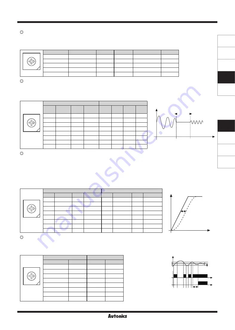
S.F: Speed Filter / Limit setting switch
-Depending on TM switch setting, speed filter and speed limit function can be set.
● Speed Filter
-In standard mode, it sets the delay time between the command position and the motor position.
- It determines the responsiveness of the motor to the command and smoothly follows the speed even if the load changes or disturbance occurs.
● Speed Limit
-In torque mode, it sets the speed limit.
- When the rotation speed reaches the speed limit value, the torque control may become unstable. Set value greater than the speed to be limited.
8
0
4
C
6
E
2
A
1
9
3
B D
5
7
F
GAIN
GS H/L OFF
GS H/L ON
Setting Standard
GAIN
Setting Standard
GAIN
Setting Inertia
GAIN Setting
Inertia
GAIN
0
×1
8
×9
0
×17
8
×25
1
×2
9
×10
1
×18
9
×26
2
×3
A
×11
2
×19
A
×27
3
×4
B
×12
3
×20
B
×28
4
×5
C
×13
4
×21
C
×29
5
×6
D
×14
5
×22
D
×30
6
×7
E
×15
6
×23
E
×31
7
×8
F
×16
7
×24
F
×32
8
0
4
C
6
E
2
A
1
9
3
B D
5
7
F
GAIN
Speed Filter (TM OFF)
Speed Limit (TM ON)
Setting Delay time Setting Delay time Setting Limit speed Setting Limit speed
0
Disable
8
60 ms
0
10 rpm
8
90 rpm
1
2 ms
9
80 ms
1
20 rpm
9
120 rpm
2
4 ms
A
100 ms
2
30 rpm
A
150 rpm
3
6
ms
B
120 ms
3
40 rpm
B
200 rpm
4
8
ms
C
140 ms
4
50 rpm
C
250 rpm
5
10 ms
D
160 ms
5
60 rpm
D
300 rpm
6
20 ms
E
180 ms
6
70 rpm
E
380 rpm
7
40 ms
F
200 ms
7
80 rpm
F
500 rpm
Speed
GAIN
Proper
GAIN
Over
Under
Status
INP: In-Position setting swtich
8
0
4
C
6
E
2
A
1
9
3
B D
5
7
F
INP
Fast response
Accurate response
Setting
Value
Setting
Value
0
(factory default) 0
8
0
1
±1
9
±1
2
±2
A
±2
3
±3
B
±3
4
±4
C
±4
5
±5
D
±5
6
±
6
E
±
6
7
±7
F
±7
In-Position
(fast response)
In-Position
(accurate response)
Time
Position
Delay time: 50ms
Command
position
Time
-
After position command pulse has finished, if the gap between target position and real position is under In-Position setting value, positioning
completion pulse is output.
-Modified setting values are not applied in the running status, and the values will be applied after motor stopped.
<Graph for input speed
and motor response>
Delay time
Motor position
Input pulse
position
Time
Position


