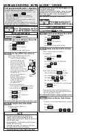
background image


14


Changing


the


belts


on


an


AutoGate


Ver cal


Pivot


operator


is


easy


by


following


the


step


by


step


procedure


outlined


below.


As


al-

ways,


we


are


only


a


phone


call


away


should


you


need


assistance


at


800-944-4283.


1.


Remove


the


(4) Tek


Screws


on


the


Top Panel


using


a


5/16”


nut


driver,


remove


and


set


aside.


2.


Remove


the


STIFFENER PLATE


(#1)


from


the


POISITION SENSOR bracket

.


This


allows


a


space


to


remove


belts.


3.


Release


the


MOTOR DRIVE BELT


(#2)


tension


by


loosening


the


(4) 3/8” CARRIAGE BOLT nuts


securing


the


GEAR MOTOR


bracket (#3)


to


the


SIDE SLIDE


plates (#4)


with


a


9/16”


wrench.


Now


using


a


9/16”


wrench,


back


o

ff 

the


(2) Gear Motor 

FORCING screws


(#5)


so


that


only


1”


remains


through


the


coupling


nut.


4.


Slide


the


GEAR MOTOR assembly


to


create


slack


in


the


belts.


5.


On


the


center


of


the


pulleys.


Loosen


the


FLANGE BEARING bolts


(#6)


about


one


turn


that


secure


the


sha


bearings


using


a


15/16”


wrench.


6.


Loosen


the


MIDDLE FORCING screw


(#7) 

which


is


applying


tension


on


the


GATE DRIVE belts


(#8) 

by


using


a


15/16”


wrench.


This


too


needs


to


be


fully


loosened


to


allow


enough


room


to


remove


the


belts.


7.


Remove


old


belts


and


install


new


belts


loosely.


8.


Apply


snug


pressure


to


the


MOTOR DRIVE belts


by


using


the


(2) GEAR MOTOR FORCING screws

.


This


should


also


snug


the


GATE DRIVE belts

.


Do not over ghten!


9.


Thread


the


MIDDLE FORCING screw


to


fi

nger


ght.


10.


Re-Assemble


the


STIFFNER PLATE


to


the


POSITION SENSOR bracket

.


11.


Operate


the


gate


up


and


down


for


(5)


me


to


seat


the


belts.


12.


Tighten


the


MIDDLE FORCING screw


to


ghten


the


GATE DRIVE belts

.


SEE PAGE 3 FOR BELT TENSION INFORMATION


13.


Tighten


the


FLANGE BEARING bolts


on


the


middle


set


of


pulleys.


14. 

Tighten


the


GEAR MOTOR FORCING screw


SEE PAGE 3 FOR BELT TENSION INFORMATION 

15.


Tighten


the


(4) CARRIAGE bolts


to


secure


the


GEAR MOTOR bracket


to


the


SIDE SLIDE plates

.


16.


Operate


the


gate


up


and


down


5-10


mes


to


check


for


proper


opera on.


17.


Replace


the


Top Panel


using


the


(4)


Tek


screws.


1.


S

ener


Plate


2.


Motor


Drive


Belt


3.


Gear


Motor


4.


Side


Slide


5.


Gear


Motor


Forcing


Screws


6.


Flange


Bearing


Bolts


7.


Middle


Forcing


Screw


8.


Gate


Drive


Belts


1


2


4


3


6


5


7


8


Содержание VPG2490

Страница 1: ...1 2490 GENESIS Introduction MODEL VPG2490 FULL SIZE MANUAL AVAIALBLE TO DOWNLOAD AND PRINT AT WWW AUTOGATE COM...

Страница 2: ...figura on The new configura on will provide be er control of the gate mo on and will prevent the gate from OVERRUNNING the motor There will be 2 drive configura ons used The standard speed will open o...

Страница 3: ...keep the motor moun ng as sembly square either using a tape measure or the notches in the moun ng slides When properly aligned belt tension should be the same in all three belts The GATE drive belt o...

Страница 4: ...of the pow er supply The board will s ll control the gate as normal but the motor will run from the ba ery ba eries The on board charging system will now charge the ba eries from the solar panels when...

Страница 5: ...e input or an over load of the amp draw on the output The power supplies have a built in overload protec on to prevent damage to itself or the control board If the power supply over heats it will shut...

Страница 6: ...it switches P14 Loop Rack Accessory Wiring harness port Used with our LR 3 Loop Rack board J1 USB For data connec on future use P6 Program Plug Used to update board so ware cont P4 P5 Pg 7 8 P1 Pg 6 P...

Страница 7: ...24VDC Fused Accessory Power 12VDC Fused Accessory Power SPECIAL NOTE The GENESIS board can be retro fit into older operators If a Genesis board is to be used in non monitored entrapment device gate s...

Страница 8: ...at full open un l an INTENDED INPUT is ac vated Keypad Reader Push Bu on Free Exit The close command will close the gate and clear the hold command An Open command or a Reverse command not the Close...

Страница 9: ...the open posi on When in constant pressure mode close input responds on ini al press Not com mon on Ver cal Pivot Gate If held in upward mo on no e ect If held in downward mo on gate movement is paus...

Страница 10: ...Ac ve for condi ons related to UL325 specifica ons Lock Programmable Selectable Magne c lock op on Ac ve when the gate is closed Solenoid Interlock op on Momentary ac va on to open the bolt that mech...

Страница 11: ...o move OPEN Pulse on Motor CLOSE 2 second Pulse when gate starts to CLOSE Hold on Motor OPEN Latches Relay on when gate is OPENING Hold on Motor CLOSE Latches Relay ON when gate is CLOSING P12 P13 AUX...

Страница 12: ...e properly set when it leaves the factory If you need to adjust it refer to the instruc ons below If you need to replace contact AutoGate ADJUSTING THE LIMIT POSITION SENSOR 1 In programming mode Set...

Страница 13: ...ear and ghtness See page 44 for instruc ons Every 6 months Charge voltage for ba eries should be 27 5 VDC with ba eries disconnected check at ba ery in maintenance menu Every 6 months Check ba ery wat...

Страница 14: ...on the GATE DRIVE belts 8 by using a 15 16 wrench This too needs to be fully loosened to allow enough room to remove the belts 7 Remove old belts and install new belts loosely 8 Apply snug pressure to...

Страница 15: ...n bolt NOTE Grease fitting must point down Tighten bottom nut NOTE Chain MUST remain level and not twisted once tightened 10 Remove T M pin and restore AC DC power 11 Lowering the gate Initiate the ga...

Страница 16: ...ides top bo om of the Slide Assembly Angle 2 Only adjust the nuts 3 to 4 turns 1 4 at a me and check your amperage readings a er each adjustment NOTE your Amps in the OPEN mode should be approximately...

Отзывы: