


8
17
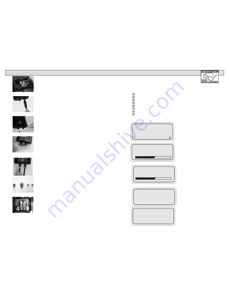
BATTERY REPLACEMENT
When the LCD indicates a low internal battery, the BVA-260 will shut down
and not operate until the 9 volt battery is replaced. Remove rubber insulator
boot, then remove the back cover and replace the battery.
ALTERNATOR TEST
This test measures the output of the charging systems under load condi-
tions. This information provides the basis for further charging system tests.
It also detects the presence of an open or shorted diode that causes an
output loss of several amps and can cause the failure of other diodes.
Symptomatic Check before Proceeding:
Battery should be in good condition and charged before testing the Charging System.
Check warning light indications.
Check belt condition and tension.
Check all cables and connections.
Check the battery for corrosion and dirty terminals.
Does the battery have a low state of charge? (See section 2 and 3)
Make sure all electrical items are off.
Check for Alternator noise.
Allow the alternator test to finish.
Test result will appear. The following are examples.
Alternator has GOOD
regulation and GOOD
output.
High Regulation will damage the
system. High Regulation is likely due
to a faulty alternator and/or voltage
regulator.
Bar at the bottom of the screen will
show the tests progress.
The BVA-260 will allow the voltage
to stabilize before starting the test
bar at the bottom of the screen that
shows the test progress. Be patient,
it can take up to 30 seconds for the
voltage to stabilize.
Use the (+Up) and (-Down) arrows to
move cursor to the desired test.
#43 12V CHARGE
PASS REGULATOR
PASS DIODES
PASS OUTPUT
#43 12V CHARGE
FAIL REG HIGH
PASS DIODES
TESTING ALTERNATOR
PLEASE WAIT…
ALLOW VOLTAGE
TO STABILIZE
14.43
BATTERY TEST
STARTER TEST
>ALTERNATOR TEST
REVIEW/PRINT
5.
Remove the 10 mm hex head bolt, lock washer,
and flat washer from the negative side current lead
using an 10 mm drive socket.
6.
Unthread both cable strain reliefs from the tester,
and pull both cables out of the tester.
7.
Remove rubber insert from both threaded fittings
on tester.
8.
Cut off small plastic fingers from both threaded
fittings using a wire cutter.
9.
Insert cables through threaded fittings. Fittings
have a slot on the inside to clear the terminal. Align the
terminal with the slot when inserting the cable through
threaded fitting.
10. Continue installing replacement cable and clamp
assemblies in reverse order of removal. Note hardware
assembly order. (Fastener, lock washer, then flat washer)
11. Tighten hardware. Recommended torque:
a. 8 mm and 10 mm hex head screws: 22 IN. LBS.
b. Phillips head Volt lead screws: 6 IN. LBS


