background image

PAG E   8

A M I S   Z R M 4   I N S TA L L AT I O N   &   O P E R AT I O N   M A N UA L

TO N E   C O N T R O L S

Each input channel includes bass and treble trim pots which may be

used to adjust the tone of the signal. The bass trim /- 12dB of

cut/boost to signals at 100Hz. The treble trim /- 10dB of

cut/boost to signals at 10kHz.

Using the bass cut in association with the high pass filter is useful for

further reduction of rumble from microphones.

NOTE: Attempting to add bass to systems that can not

reproduce bass well (such as transformer coupled

ceiling speakers or horn speakers) will only reduce

the headroom of the system and contribute to

distortion.

NOTE: adding bass or treble boost may cause the

input to clip, so keep an eye on the input’s status LED,

and reduce the gain trim if required.

P R I O R I T Y   OV E R R I D E

Each output channel has the ability to mute all other input signals in 

the selected output when there is signal present on channel #1, 

if channel #1 is assigned to that output. To enable this function activate

(press in) the "CH1 Priority Enable" switch for the required output and

assign channel #1 to that output. This is useful for paging microphones,

juke boxes and other situations where an occasional signal needs to

interrupt the normal programme.

R E M OT E   VO L U M E   C O N T R O L

The level of each output may be controlled via a RC1 remote level

control panel or 500k ohm log (A) pot. For each output there are two

pins on the connector labeled VCA on the rear panel. The RC1or 500k

ohm log (A) pot should be connected to these pins. Please note that the

remote level control inserts before and in-line with the output level

control so the RC1 sets the maximum output level (for normal signals)

and the front panel master attenuates from that level. Also note that 

an RC1 control will have no effect on the signals from input channel #1

or any of the tones generated by the tone module This is so that 

the paging can not be turned off in a zone it has been assigned to. 

If paging is too loud in a zone, the master output level control for 

that zone should be turned down.

NOTE: If using a 500k ohm pot, the connections should

be made to the wiper terminal and the anti-clockwise

terminal. i.e. max resistance = max volume

TO N E   M O D U L E

The tone module generates four separately triggerable and

priorioritised tones. They are listed in order of highest to lowest

priority. Each tone is triggered by shorting the "COM" pin of the tone

module control lines connector to its associated pin.

EVAC -  An evacuation signal. Triggered by shorting the EVAC pin to 

the COM pin. The EVAC signal will continue until the short is removed.

Triggering the EVAC signal will mute all inputs except channel #1.

ALERT - An ALERT/alarm signal. Triggered by shorting the "ALERT" 

pin to the "COM" pin. The ALERT signal will continue until the short 

is removed. Triggering the alarm signal will mute all inputs except

channel #1.

BELL - A chime like a BELL being struck twice, a short gap and then

repeated. Triggered by shorting the "BELL" pin to the "COM" pin. 

The BELL signal will continue until the short is removed.

PRE-ANNOUNCE - A four note chime, suitable for use before a 

page is made. Triggered by shorting the "PRE" pin to the "COM" pin. 

The PRE-ANNOUNCE chime will sound only once for each time 

the chime is triggered.

NOTE: The bell and pre-announce chimes are routed

with signals from channel #1, thus any output which

has channel #1 assigned to it will also receive these

tones. The EVAC and ALERT signals are routed to all

outputs AFTER the level controls. This is to ensure

that all zones receive these tones.

NOTE: Because EVAC and ALERT do not mute channel

#1, it is not advisable to connect a continuous source

(such as a radio or CD player) to this input.

A DVA N C E D   F E AT U R E S

Содержание AMIS ZRM4

Страница 1: ...ralian Monitor 1 Clyde Street Silverwater NSW 2128 Australia 61 2 9647 1411 www australianmonitor com au SERVICE INFORMATION ZRM4 ROUTING MIXER CONTENTS OPERATION MANUAL SCHEMATIC DIAGRAMS SERVICE BULLETIN ...

Страница 2: ...6 X 4 ROUTING MIXER INSTALLATION AND OPERATION MANUAL AMIS ZRM4 ...

Страница 3: ......

Страница 4: ... installed in remote zones allowing for a volume range from off to whatever the master level on the AMIS ZRM4 relevant zone output is set to Alert Evacuation Bell Pre Announce tones are provided on board The AMIS ZRM4 is a compact yet extremely versatile zone routing mixer which makes the complex task of multizone signal routing simple cost effective INTRODUCTION 3 FRONT PANEL 4 REAR PANEL 5 INTER...

Страница 5: ...there is signal present and red if the signal is approaching clip The LED begins to light red when the internal signal level is 6dB before clip and is solid red when it is 3dB before clip Note that the front panel level control is post status LED and as such the status LED is NOT affected by the level control See internal adjustment section on page 6 OUTPUT CONTROL SECTION OUTPUT LEVEL CONTROLS Th...

Страница 6: ...ONS These connections are used to trigger the internal tones Only one tone can be triggered at a time Triggering occurs by connecting the ALERT EVAC BELL or PRE terminal to COM The pre announce and bell tones are routed along with input channel 1 whilst the evac and alert tone are always routed to all outputs VCA Each output level may be controlled by a RC1 remote wall panel or 500k ohm log A pot ...

Страница 7: ... the XLR input is suitable for use with microphones in the LINE position the XLR input is suitable for use with a balanced line level signal NOTE Both MIC LINE switches must be in the same position for correct operation of the balanced input The MIC LINE switches only affect the XLR input GAIN TRIM The input gain can be cut or boosted by up to 15dB using this control This control affects both the ...

Страница 8: ...designated priority input NOTE The high pass filter has a knee around 160Hz and a roll off of 6dB octave Using the HPF helps to eliminate thumps and rumble often heard through paging mics CONNECT THE OUTPUTS Turn the amplifiers off Connect the AMIS ZRM4 s outputs to the amplifiers line level input Check that the AMIS ZMR4 is on then turn on the amplifiers If the amplifiers have a level controls se...

Страница 9: ...l will have no effect on the signals from input channel 1 or any of the tones generated by the tone module This is so that the paging can not be turned off in a zone it has been assigned to If paging is too loud in a zone the master output level control for that zone should be turned down NOTE If using a 500k ohm pot the connections should be made to the wiper terminal and the anti clockwise termi...

Страница 10: ...AMIS ZRM4 INSTALLATION OPERATION MANUAL PAGE 9 BLOCK DIAGRAM ...

Страница 11: ...PAGE 10 AMIS ZRM4 INSTALLATION OPERATION MANUAL SPECIFICATIONS ...

Страница 12: ...or 24 to 34v DC regulated 600mA max SENSITIVITY input required for 0dBu out RCA IN 26dBu to 4dBu 39mV to 1 23 V XLR LINE IN 26dBu to 4dBu 39mV to 1 23V XLR MIC IN 60dBu to 30dBu 0 78mV to 25mV MAX LEVEL IN 14 1Vrms 25dBu MAX LEVEL OUT 15 4Vrms 26dBu FREQUENCY RESPONSE 5Hz to 22kHz 0dB 3dB THD less than 0 1 NOISE 90dBu 20Hz 20kHz all pots centred CROSSTALK 65dB 1kHz PHANTOM POWER 15VDC ...

Страница 13: ... Email sa audiotelex com au PERTH WA SALES 299 Fitzgerald Street West Perth WA 6005 PO Box 404 North Perth WA 6906 Phone 08 9228 4222 Fax 08 9228 4233 Email wa audiotelex com au AUCKLAND NZ SALES Unit B 11 Piermark Drive Albany 1331 New Zealand PO Box 512 Albany 1331 Phone 09 415 9426 Fax 09 415 9864 Email audiotlx nznet gen nz AUSTRALIA AND NEW ZEALAND www australianmonitor com au INTERNATIONAL S...

Страница 14: ...01A LM833N 8 5 6 7 4 8 IC201B LM833N 8 15 15 15 15 R201 4k7 R202 4k7 R203 100k R214 22k C201 10u C202 10u C203 10u R207 680 R204 680 R209 33k R208 33k SW201A SW201B SW201C SW201D R213 22k C206 47p C207 47p 15 R205 5k6 R206 5k6 C204 1u R211 4k7 R210 18k R212 6k8 C205 22p CW CCW VR201 47k X201 3 CW CCW VR204 47K CW CCW VR203 47K C211 33n C212 2n7 R224 10k X201 1 X201 2 5 6 7 4 8 IC202B LM833N 8 4 8 ...

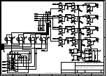
Страница 15: ...3N 8 5 6 7 4 8 IC401B LM833N 8 15 15 15 15 R401 4k7 R402 4k7 R403 100k R414 22k C401 10u C402 10u C403 10u R407 680 R404 680 R409 33k R408 33k SW401A SW401B SW401C SW401D R413 22k C406 47p C407 47p 15 R405 5k6 R406 5k6 C404 1u R411 4k7 R410 18k R412 6k8 C405 22p CW CCW VR401 47k X401 3 CW CCW VR404 47K CW CCW VR403 47K C411 33n C412 2n7 R424 10k X401 1 X401 2 5 6 7 4 8 IC402B LM833N 8 4 8 2 3 1 IC...

Страница 16: ...3N 8 5 6 7 4 8 IC601B LM833N 8 15 15 15 15 R601 4k7 R602 4k7 R603 100k R614 22k C601 10u C602 10u C603 10u R607 680 R604 680 R609 33k R608 33k SW601A SW601B SW601C SW601D R613 22k C606 47p C607 47p 15 R605 5k6 R606 5k6 C604 1u R611 4k7 R610 18k R612 6k8 C605 22p CW CCW VR601 47k X601 3 CW CCW VR604 47K CW CCW VR603 47K C611 33n C612 2n7 R624 10k X601 1 X601 2 5 6 7 4 8 IC602B LM833N 8 4 8 2 3 1 IC...

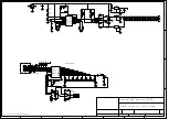
Страница 17: ...C40 10u C13 47p R12 10k R11 10k OUTPUT A OUTPUT B OUTPUT C OUTPUT D SW1A SW2A SW3A SW4A R94 470R R93 470R R92 470R R91 470R X2 12 X2 11 X2 10 X2 9 5 6 7 4 8 IC17B LM833N 8 C34 100u C33 100u C35 100u C36 100u X2 5 X2 6 X2 7 X2 8 GP1 6 GP0 7 gnd 8 5 1 GP5 2 GP4 3 GP3 4 GP2 5 PIC12F675 IC10 PIC12F675 GP1 6 GP0 7 gnd 8 5 1 GP5 2 GP4 3 GP3 4 GP2 5 PIC12F675 IC9 PIC12F675 D7 D8 D9 D10 D5 2v7 D6 2v7 X1 9...

Страница 18: ...MES ALARMS 15 15 5 5 MUTE 5 R700 100 X4 5 CORE RIBBON CABLE 1 X5 PCB6337 Tone module triggers Tone Generator R57 1k R56 1k R47 1k R48 1k 5 V1 V2 R9 220R R10 220R TR1 R8 220R R7 220R D1 D2 D4 D3 C8 470u RW 5 RH 3 U D 2 INC 1 GND 4 5 8 RL 6 CS 7 IC15 X9313 C1 10n C2 1n R2 22k R5 10k R6 22k C3 100n C4 470u C9 470u IN gnd OUT IC4 LM7815 IN gnd OUT IC2 LM7805 C11 100u C7 100u C10 100u IN gnd OUT IC3 LM...

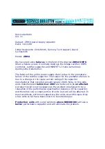
Страница 19: ...eason for the premature failure is due to a change in the ripple current rating of the capacitor manufacturer that occurred around January 2008 Note to this date units manufactured before Dec 2007 are believed to be unaffected A product recall is not necessary as the problem is believed to be a relaxation of the performance specification tolerance of the capacitor and therefore only a small portio...

Страница 20: ...ion Failures modes include a total failure of the bridge rectifier BR1 IC1 MOSFET devices V1 and V2 C8 and C9 Solution Replacement of the electrolytic capacitors in the power supply section with higher operating temperature low impedance parts is recommended in the interest of longevity and reliable operation Replace the critical component as per the table below Recommended Part Designators Value ...

Отзывы: