The limitation of travel is realised via limit switches
(page 13) in both end positions. For this reason the end
stops of the actuator have to be set to a slightly larger swing
angle (approx. by 2° larger) than the swing angle actually
required by the valve.
9.
Electrical connection
Work on the electrical system or equipment must only be
carried out by a skilled electrician himself or by specially
instructed personnel under the control and supervision of
such an electrician and in accordance with the applicable
electrical engineering rules.
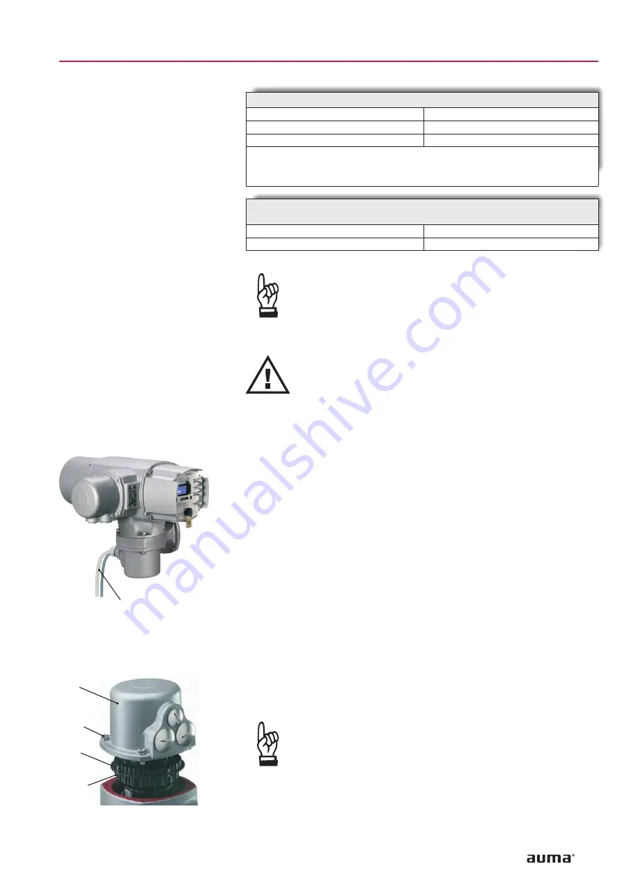
AUMA part-turn actuators SG are operated via the controls AUMATIC
AC 01.1. The controls may either be mounted directly to the actuator or to a
separate wall bracket.
When installing the AUMATIC on a wall bracket, observe the following points:
.
For the connection of actuator and AUMATIC on wall bracket, use suitable
flexible and screened connecting cables.
(Connecting cables are available on request, see address list page 68).
.
The max. permissible cable length between actuator and the controls
AUMATIC is 100 m.
9.1
Connection with AUMA plug/socket connector
.
Check whether type of current, supply voltage and frequency correspond
to motor data (refer to name plate at motor/AUMATIC).
.
Loosen bolts (26.01) (figure C2) and remove plug cover (26.0).
.
Loosen screws (26.2.5) and remove socket carrier (26.2) from plug cover
(26.0).
.
Insert cable glands suitable for connecting cables.
.
Enclosure protection IP 67 or IP 68 is only ensured if
suitable cable glands are used.
.
Seal cable entries which are not used with suitable plugs.
11
Part-turn actuators SG 03.3 – SG 04.3
Operation instructions
with AUMATIC AC 01.1
Fig.C1 Wall bracket (accessory)
Connecting cables to actuator
Fig. C2: Connection
26.0
26.01
26.2
26.2.5
Basic factory setting for 90° swing angle:
Swing angle
1)
SG 03.3/SG 04.3
Dimension T (factory setting)
mm
13.5
Dimension T
min.2)
mm
9
1) By turning at the hex. socket head cap screw for end stop CLOSED or OPEN the end
position changes accordingly.
The swing angle can be checked and set by using the dimension T.
2) If T
min.
is not reached, the gearing might be damaged.
For each turn of the hex. socket head cap screw, the setting of the end
position changes by:
for clockwise turn approx.:
3.3°
for counter-clockwise turn approx.:
2.4°


