


2.
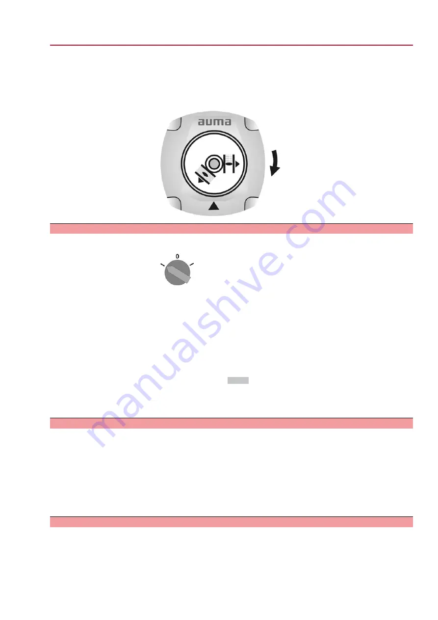
Switch on actuator in direction CLOSE and observe the direction of rotation on
the indicator disc.
→
Switch off before reaching the end position.
➥
The direction of rotation is correct, if actuator runs in direction CLOSE and
indicator disc turns clockwise.
9.9.2
Limit switching: check
1.
Set selector switch to position Local control (LOCAL).
2.
Operate actuator using push buttons OPEN - STOP - CLOSE.
➥
The limit switching is set correctly if (default indication):
-
the yellow indication light/LED1 is illuminated in end position CLOSED
-
the green indication light/LED5 is illuminated in end position OPEN
-
the indication lights go out after travelling into opposite direction.
➥
The limit switching is set incorrectly if:
-
the actuator comes to a standstill before reaching the end position
-
one of the red indication lights/LEDs is illuminated (torque fault)
-
the status indication
S0007
in the display signals a fault.
3.
If the end position setting is incorrect: Reset limit switching.
4.
If the end position setting is correct and no options (e.g. potentiometer, position
transmitter) are available: Close switch compartment.
9.9.3
Reference operation position feedback: perform
For actuators with position feedback (RWG, potentiometer), a reference operation
has to be performed once the limit switching setting was changed to ensure that the
position feedback (0/4 – 20 mA) supplies correct values:
→
Operate actuator electrically (via the push buttons OPEN and CLOSE of the local
controls) once to end position OPEN and once to end position CLOSED.
If no reference operation is performed after changing the limit switching, the feedback
signal via the bus is not correct. The bus signals the missing reference operation as
a warning.
9.10
Potentiometer setting
— Option —
The potentiometer as travel sensor records the valve position.
Information
Due to the ratio of the reduction gearing the complete resistance range/stroke is not
always passed. Therefore, external adjustment (setting potentiometer) must be pro-
vided.
53
SGExC 05.1 – SGExC 12.1 Control unit: electromechanic
ACExC 01.2 Intrusive Modbus RTU
Commissioning (basic settings)
Содержание AUMATIC ACExC 01.2
Страница 84: ...84 SGExC 05 1 SGExC 12 1 Control unit electromechanic Certificates ACExC 01 2 Intrusive Modbus RTU...
Страница 85: ...85 SGExC 05 1 SGExC 12 1 Control unit electromechanic ACExC 01 2 Intrusive Modbus RTU Certificates...
Страница 86: ...86 SGExC 05 1 SGExC 12 1 Control unit electromechanic ACExC 01 2 Intrusive Modbus RTU...
Страница 87: ...87 SGExC 05 1 SGExC 12 1 Control unit electromechanic ACExC 01 2 Intrusive Modbus RTU...