M 2.1AMP
1-Kanal / 2-Kanal Miniatur-Verstärker
1 ch / 2 ch Micro Amplifier
deutsch / english
micro
Страница 1: ...M 2 1AMP 1 Kanal 2 Kanal Miniatur Verstärker 1 ch 2 ch Micro Amplifier deutsch english micro ...
Страница 2: ...lsicherheit muss der Verstärker professionell befestigt werden Dieses geschieht über Schrauben die in eine Montagefläche ein geschraubt werden die wiederum genügend Halt bieten muss Bevor Sie die Schrauben im Montage feld befestigen vergewissern Sie sich dass keine elektrischen Kabel und Komponenten hydraulische Bremsleitungen der Benzintank etc dahinter ver borgen sind Diese könnten sonst beschäd...
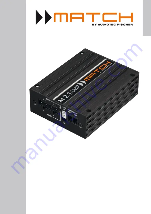
Страница 3: ...ine Input Cinch Eingänge zum Anschluss eines Vorverstärkersignals 5 Speaker Output Lautsprecherausgänge für den Anschluss von Lautsprechersystemen 6 Mono Stereo Mode MSM LED Die LED zeigt den Betriebsmodus des Laut sprecherausgangs an Werkseitig 1 Kanal Modus LED an 7 REM IN OUT Anschluss für den Remote Ein und Aus gang 8 12 V Anschluss für das Versorgungsspannungs kabel 12 V der Batterie 9 GND An...
Страница 4: ...nt nur der Anpassung Der Regelbereich des Cinch Eingangs Line Input liegt zwischen 1 6 Volt Linksanschlag 6 Volt Rechtsanschlag 1 Volt 4 Line Input 2 Kanal Vorverstärkereingang zum Anschluss von Signalquellen wie z B Signalprozessoren oder DSP Verstärkern Achtung Verwenden Sie zum Anschluss aus schließlich das mitgelieferte Line Input Anschluss kabel siehe Seite 5 Abb 1 5 Speaker Output Diese Ansc...
Страница 5: ...ehe unten 9 GND Das Massekabel sollte am zentralen Massepunkt dieser befindet sich dort wo der Minuspol der Bat terie zum Metallchassis des Kfz geerdet ist oder an einer blanken von Lackresten befreiten Stelle des Kfz Chassis angeschlossen werden Der empfohle ne Querschnitt beträgt mindestens 6 mm Achtung Verwenden Sie zum Anschluss aus schließlich den mitgelieferten Power Input Stecker mit integr...
Страница 6: ...geschlossen werden Im Mono Modus siehe Seite 6 Punkt 1 muss dabei nur der Kanal A belegt werden In diesem wird das Ein gangssignal von Kanal A an beiden Lautspre cherausgängen ausgegeben Im Stereo Modus wird jeder der Lautsprecherausgänge mit dem dazugehörigem Eingangssignal versorgt Der aktuell aktivierte Modus wird durch die Mono Stereo Mode LED angezeigt siehe Seite 4 Punkt 6 3 Einstellung der ...
Страница 7: ...sorgung Vor dem Anschluss des 12 V Versorgungs kabels an das Bordnetz muss die Autobatte rie abgeklemmt werden Das 12 V Stromkabel ist am Pluspol der Bat terie anzuschließen Die Plusleitung sollte in einem Abstand von max 30 cm von der Batte rie mit einer Hauptsicherung abgesichert wer den Der Wert der Sicherung errechnet sich aus der maximalen Stromaufnahme der gesamten Car Hifi Anlage M 2 1AMP m...
Страница 8: ...ssen im vorgeschalteten DSP DSP Verstärker eingestellt werden Konfigurationsbeispiele Mono Mode DSP oder DSP Verstärker Beispiel 2 1 Kanal Subwoofer Anwendung Subwoofer mit einer Schwingspule Subwoofer A A Beispiel 1 1 Kanal Subwoofer Anwendung Subwoofer mit Doppelschwingspule SW Schwingspule Min Impedanz 2 x 4 Ω Daraus ergibt sich eine min Gesamtimpedanz von 2 Ω SW 2 SW 1 Subwoofer A A Min Gesamt...
Страница 9: ...P DSP Verstärker eingestellt werden Konfigurationsbeispiele Stereo Mode DSP oder DSP Verstärker Beispiel 3 2 Kanal Tiefton Anwendung Zwei Subwoofer mit einer Schwingspule oder zwei Tiefmitteltonlautsprecher Subwoofer L Subwoofer R A Subwoofer R Subwoofer L B A B Beispiel 4 2 Kanal Fullrange Anwendung Passives Komponenten oder Koaxialsystem Rechts Links Rechts Links A B A B Min Impedanz pro Lautspr...
Страница 10: ...le Eingangsempfindlichkeit geregeltes Netzteil Start Stopfähigkeit Masseschalter Mono Stereo Modus Abmessungen H x B x T 35 x 85 x 110 mm Die Garantieleistung entspricht der gesetzlichen Regelung Von der Garantieleistung ausgeschlos sen sind Defekte und Schäden die durch Überla stung oder unsachgemäße Behandlung entstanden sind Eine Rücksendung kann nur nach vorheriger Absprache in der Originalver...
Страница 11: ...mplifier may only be in stalled in vehicles which have a 12 Volts negative terminal connected to the chassis ground Any oth er system could cause damage to the amplifier and the electrical system of the vehicle The positive cable from the battery for the complete system should be provided with a main fuse at a distance of max 30 cm from the battery The val ue of the fuse is calculated from the max...
Страница 12: ...RCA Cinchinputsforconnecting pre amplifier signals 5 Speaker Output Speaker outputs for connecting speaker systems 6 Mono Stereo Mode MSM LED This LED indicates the operating mode of the Speaker Output Default setting 1 channel mode LED off 7 REM IN OUT Connector for the remote in and output 8 12 V Connector for the 12 V power cable of the positive terminal of the battery 9 GND Connector for the g...
Страница 13: ...amplifier input to connect signal sourc es such as DSPs DSP amplifiers Attention Solely use the Line Input connection cable see page 15 fig 1 which is included in delivery 5 Speaker Output Speaker outputs to connect speaker systems The M 2 1AMP is equipped with a Mono Stereo Mode This allows to operate the amplifier as 1 or 2 channel amplifier The Mono Mode is activated by default By removing a ju...
Страница 14: ... mon ground reference point this is located where the negative terminal of the battery is grounded to the metal body of the vehicle or to a prepared metal location on the vehicle chassis i e an area which has been cleaned of all paint residues Rec ommended cross section min 6 mm AWG 10 ...
Страница 15: ...eo Mode am plifier The Mono Mode is activated by default To activate the Stereo Mode the device has to be opened and a jumper must be removed Therefore dismantle the side panel where the Line Input is located by removing the two Phil lips screws and pull out the bottom plate side ways Now you have access to the jumper Mono Mode Jumper plugged Stereo Mode Jumper removed 1 MicroFit connector this wi...
Страница 16: ...ts The loudspeaker outputs can be connected to the wires of the loudspeakers by using the pluggable screw terminal which is included in delivery Never connect any of the loudspeaker cables with the chassis ground as this will dam age your amplifier and your speakers Ensure that the loudspeakers are correctly con nected in phase i e plus to plus and minus to minus Exchanging plus and minus causes a...
Страница 17: ... frequencies for the high and lowpass must be set in the preconnected DSP DSP amplifier DSP or DSP amplifier Example 2 1 channel subwoofer application Subwoofer with single voice coil Subwoofer A A Example 1 1 channel subwoofer application Subwoofer with dual voice coil VC voice coil VC 2 VC 1 Subwoofer A A Min impedance 2 x 4 Ω This results in a min total impedance of 2 Ω Min total impedance 2 Ω ...
Страница 18: ...in the preconnected DSP DSP amplifier DSP or DSP amplifier Example 3 2 channel subwoofer application Two subwoofers with single voice coil or two mid woofers Subwoofer L Subwoofer R A Subwoofer R Subwoofer L B A B Example 4 2 channel fullrange application Passive component or coaxial system Right Left Right Left A B A B Configuration examples Stereo Mode Min impedance per speaker 4 Ω Min impedance...
Страница 19: ...e European Union EU Technical Data Warranty Disclaimer Power RMS Mono Mode Stereo Mode 4 Ohms 1 x 210 Watts 2 x 170 Watts 2 Ohms 1 x 350 Watts Max output power Mono Mode Up to 430 Watts RMS 2 Ohms Amplifier technology Class HD Inputs 2 x RCA Cinch 1 x Remote In Input sensitivity 1 6 Volts Input impedance 10 kOhms Outputs 2 x Speaker output 1 x Remote Out Frequency range 10 Hz 40 000 Hz Signal to n...
Страница 20: ...Audiotec Fischer GmbH Hünegräben 26 57392 Schmallenberg Germany Tel 49 2972 9788 0 Fax 49 2972 9788 88 E mail match audiotec fischer com Internet www audiotec fischer com ...